


Quick Research
Generate reliable direction feasibility study reports for your R&D in just a few steps.

Technical Q&A
Discover and master advanced knowledge NOW. Basics, ideas, possibilities, all at once.

Find Solutions
As an expert in R&D theories, this can generate solutions to your technical problems instantly.

Evaluate Feasibility
Analyze your overall solution with one click, know your potential R&D risks in advance.

Monitor Landscape
Get weekly tech updates, stay abreast of the latest tech innovations and key insights.
High-efficiency air barrel generation method and system
A technology of wind power generation system and wind power generator, which is applied in wind power generation, wind power generator, and wind power generator consistent with the wind direction, etc., which can solve the problems of small loss and low investment, and achieve reduction of useless work, stable wind power output, and increase of wind speed Effect
- Summary
- Abstract
- Description
- Claims
- Application Information
AI Technical Summary
Problems solved by technology
Method used
Image

Examples
Embodiment 1
[0031] Such as Figure 1-4 shown.
[0032] A high-efficiency wind tube power generation method, it comprises the following steps:
[0033] First of all, build a vertical or horizontal large-diameter air duct; the diameter of the air duct is 6-200 meters, the best effect; the lower part or one end of the air duct is equipped with an air inlet to continuously provide fresh air for the blower;
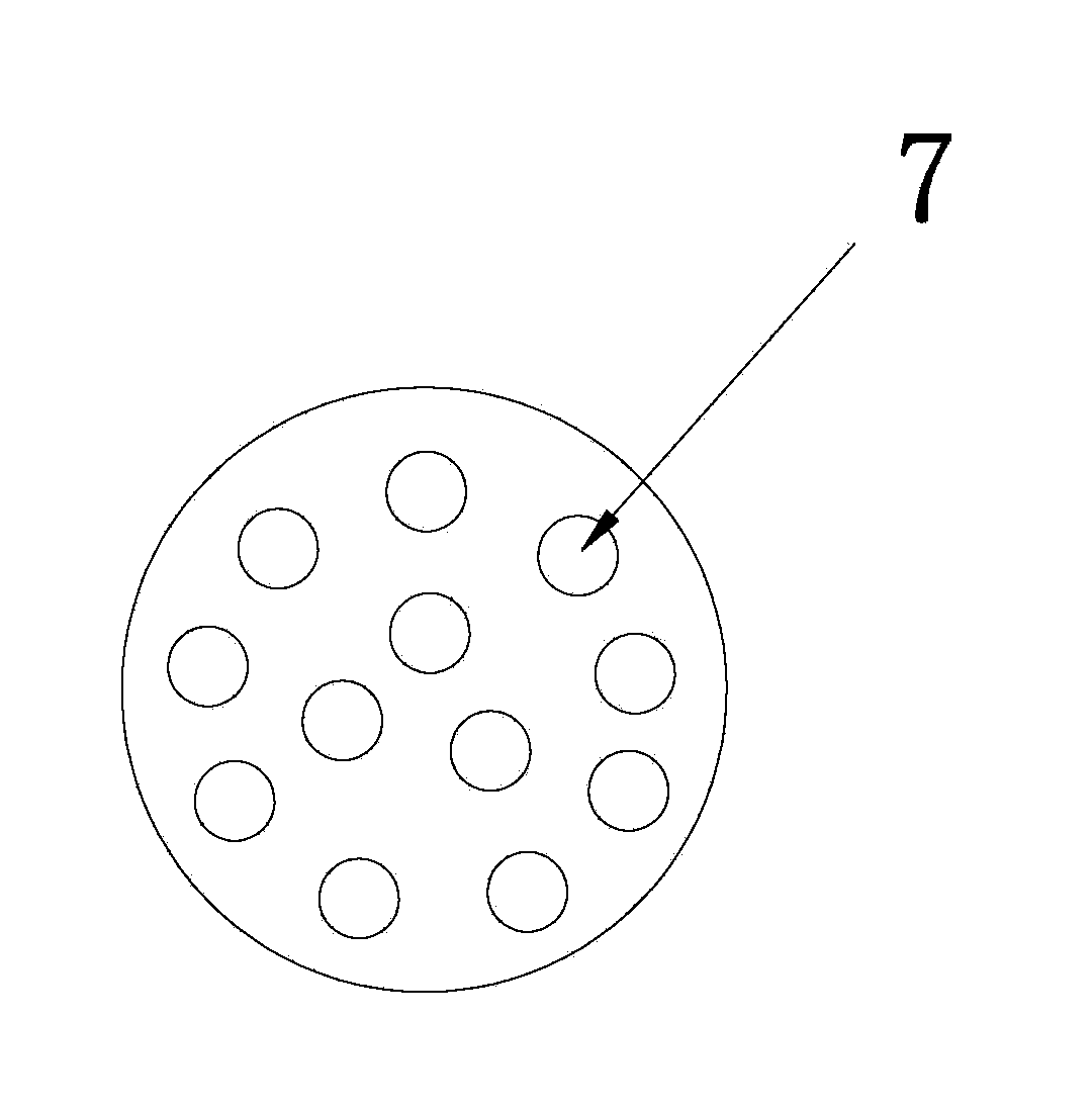
[0034] Second, install at least one array of blowers such as image 3 ;
[0035] Thirdly, install wind turbine blades with matching diameters in the air cylinder along the axial direction; in practice, multiple generators can be connected to generate electricity in the air cylinder, or installed on the same blade shaft Multiple blades are used to drive high-power generators to improve the power generation effect;
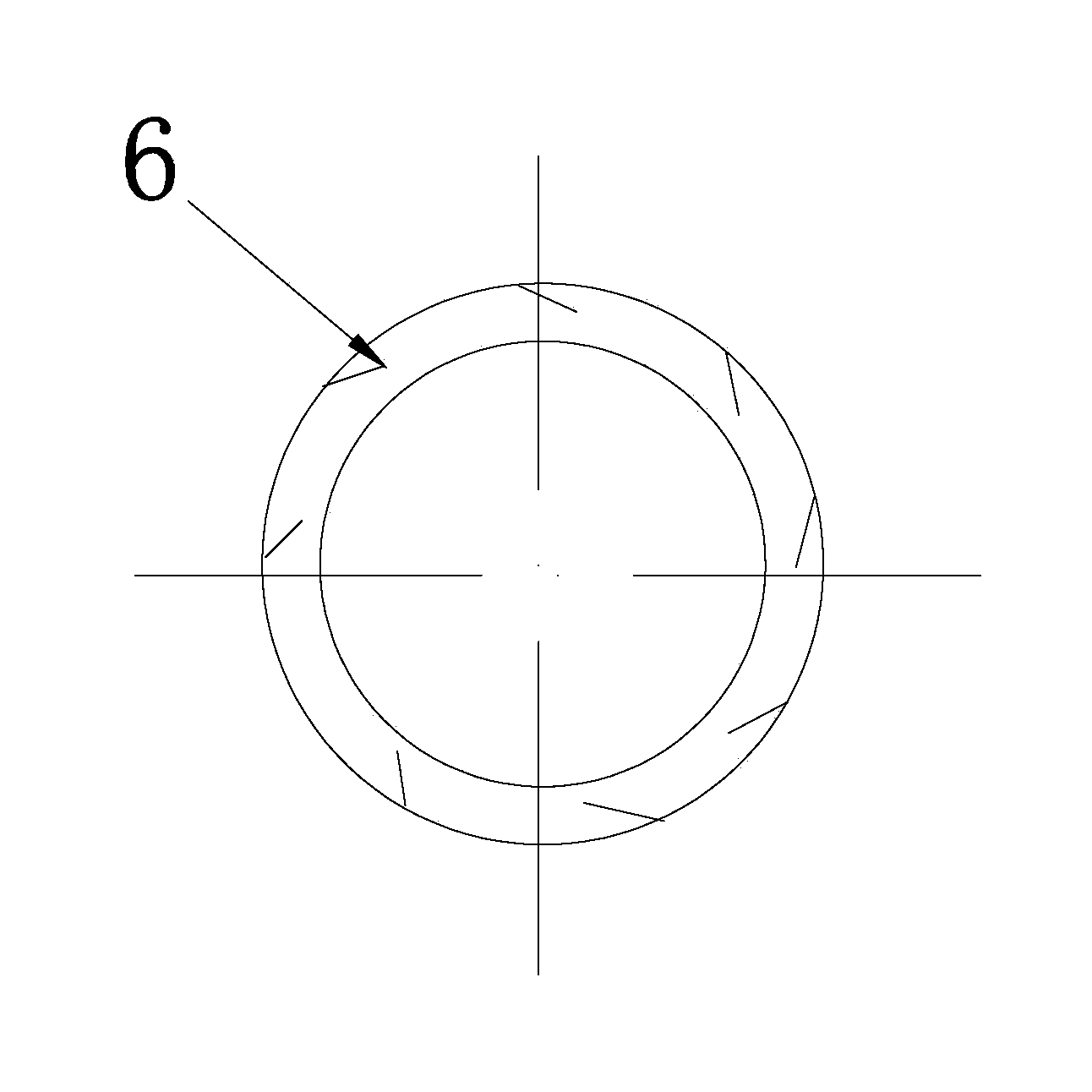
[0036] Fourth, set a central shroud with a diameter smaller than the inner diameter of the wind drum at the bottom or one side of each wind turbine blade in the wind drum. ...
Embodiment 2
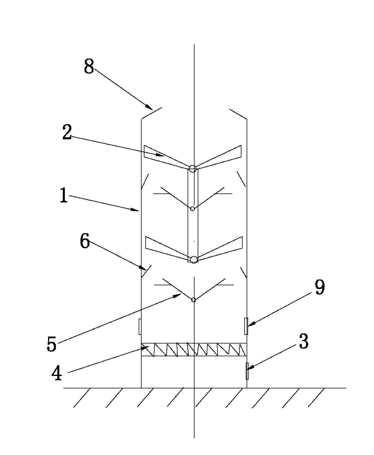
[0038] Such as Figure 1-3 shown.
[0039] A fan duct high-efficiency wind power generation system, which includes a vertical fan duct 1 and a wind generator. The diameter of the vertical duct 1 is preferably 6-200 meters. Air blower array 4, each air blower array is made up of many small air blowers 7, as image 3 , during specific implementation, according to the height of the air duct, multi-layer blower array 4 can also be set so that the wind of the air duct is pressurized, the wind-driven generator is installed in the vertical air duct, and the blade shaft of the wind-driven generator is installed in the wind duct. At the central position, wind generator blades 2 are installed on the blade shaft, and each wind generator has a blade shaft, and multiple wind generator blades can also be installed on the same blade shaft during specific implementation, so as to drive high-power The generator works, and the bottom of the vertical air cylinder 1 is provided with an air in...
Embodiment 3
[0041] Such as Figure 4 shown.
[0042] A blower duct high-efficiency wind power generation system, which includes a horizontal blower 1 and a wind generator, the diameter of the blower can be between 6-200 meters, the wind generator is installed in the horizontal blower, the blade shaft of the wind generator It is installed at the center of the horizontal air duct, and the wind turbine blade 2 is installed on the blade shaft, and multiple sets of blades can also be installed on the same blade shaft, such as Figure 4 As shown, one end of the horizontal air duct 1 is provided with an air inlet 3, and several layers of blower arrays 4 are installed on the side of the air inlet 3 towards the direction of the wind power generator, and each layer of blower arrays is composed of multiple small blowers. 7 composition such as image 3 As shown, the multi-layer blower array can be provided with corresponding air inlets separately, or can share one air inlet, and sharing one air...
PUM
 Abstract
Description
Claims
Application Information
 - R&D Engineer
- R&D Manager
- IP Professional
- Industry Leading Data Capabilities
- Powerful AI technology
- Patent DNA Extraction
Browse by: Latest US Patents, China's latest patents, Technical Efficacy Thesaurus, Application Domain, Technology Topic, Popular Technical Reports.
© 2024 PatSnap. All rights reserved.Legal|Privacy policy|Modern Slavery Act Transparency Statement|Sitemap|About US| Contact US: help@patsnap.com