
Steel plate bending equipment

A steel plate and bending technology, which is applied in the field of steel plate bending equipment, can solve the problems of uneven quality of curved steel plates, difficult control of arc bending, and extra workload, so as to improve kinetic energy utilization efficiency, simplify force, and reduce useless work.

Active Publication Date: 2018-12-28
芜湖同创模具机械有限公司
View PDF8 Cites 5 Cited by
  • Summary
  • Abstract
  • Description
  • Claims
  • Application Information

AI Technical Summary

Problems solved by technology

[0002] Most of the existing curved steel plates are formed by cold forging and stamping of flat steel plates. However, due to the lack of uniform processing technology and specifications, it is often difficult to control the curved steel plates, so that the quality of the processed curved steel plates varies.
Such a curved steel plate is likely to cause additional workload during the application construction process

Method used


Image

  • Steel plate bending equipment
  • Steel plate bending equipment

Examples


Embodiment Construction

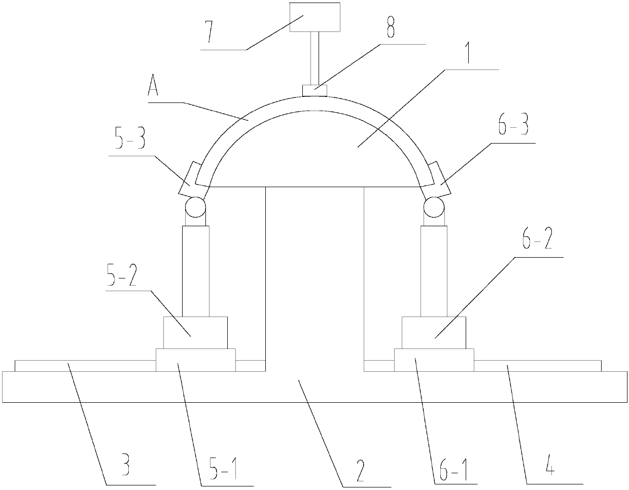
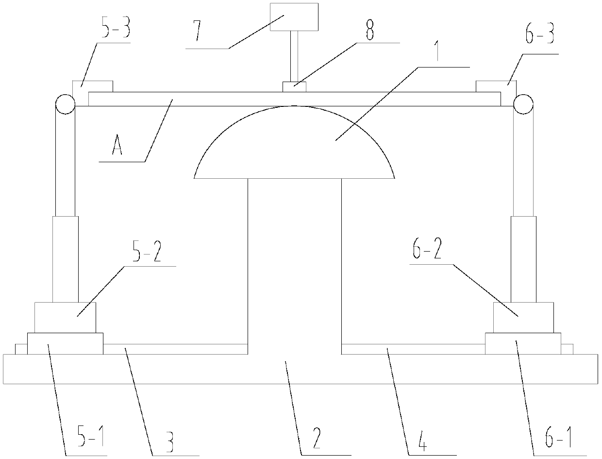
[0021] refer to figure 1 , a steel plate bending equipment proposed by the present invention includes: a punch 1 , a first press-down mechanism, a second press-down mechanism and a base 2 .

[0022] The upper surface of the punch 1 is a curved surface that fits the inner surface of the bent steel plate, and the punch 1 is fixedly installed on the base 2 . A first track 3 and a second track 4 are respectively provided on the base 2 on opposite sides of the punch 1 .

[0023] The first depressing mechanism comprises a first moving frame 5-1, a first cylinder 5-2 and a first manipulator 5-3, the first moving frame 5-1 is slidably installed on the first track 3, and the first cylinder 5-2 Installed on the first moving frame 5-1, the first manipulator 5-3 is connected with the first air cylinder 5-2, and the first air cylinder 5-2 is used to drive the first manipulator 5-3 to move up and down.

[0024] The second depressing mechanism comprises a second moving frame 6-1, a second ...


PUM


Abstract

The invention relates to steel plate bending equipment which comprises a male die, a first downward pressing mechanism, a second downward pressing mechanism and a base. The first downward pressing mechanism comprises a first moving frame, a first air cylinder and a first manipulator; the first moving frame is slidably mounted on a first track; the first air cylinder is mounted on the first movingframe; the first manipulator is connected with the first air cylinder; and the first air cylinder is used for driving the first manipulator to move up and down. The second downward pressing mechanismcomprises a second moving frame, a second air cylinder and a second manipulator. According to the steel plate bending equipment, the two opposite sides of a to-be-bent steel plate are clamped throughthe first manipulator and the second manipulator, then the first air cylinder and the second air cylinder drive the first manipulator and the second manipulator to pull the two opposite sides of the to-be-bent steel plate to be downwards bent, in this way, only the first air cylinder and the second air cylinder need to provide traction force for downward bending of the two ends of the to-be-bent steel plate, stress in the steel plate bending process is simplified, idle work is advantageously reduced, and the kinetic energy utilization efficiency is improved.

Description

technical field [0001] The invention relates to the technical field of steel plate processing, in particular to a steel plate bending equipment. Background technique [0002] Most of the existing curved steel plates are formed by cold forging and stamping of flat steel plates. However, due to the lack of uniform processing technology and specifications, it is often difficult to control the curved steel plates, and thus the quality of the processed curved steel plates varies. Such curved steel plates tend to cause extra workload during the application construction process. Contents of the invention [0003] Based on the technical problems existing in the background technology, the present invention proposes a steel plate bending equipment. [0004] A steel plate bending equipment proposed by the present invention includes: a punch, a first pressing mechanism, a second pressing mechanism and a base; [0005] The upper surface of the punch is a curved surface that fits the ...

Claims


Application Information

Patent Timeline
Patent Type & Authority Applications(China)
IPC IPC(8): B21D5/06B21D5/00
CPCB21D5/002B21D5/06
Inventor 陶文
Owner 芜湖同创模具机械有限公司
Learn More