
Head and tail moving device of scraper machine

A technology of pushing device and scraper, which is applied to conveyors, transportation and packaging, etc., can solve the problems of poor support, many potential safety hazards, unstable support, etc., and achieves reduction of pushing resistance, beautiful appearance and simple structure. Effect

Inactive Publication Date: 2017-02-01
河南中车重型装备有限公司
View PDF6 Cites 1 Cited by
  • Summary
  • Abstract
  • Description
  • Claims
  • Application Information

AI Technical Summary

Problems solved by technology

[0004] As we all know, the scraper machine is an important transportation equipment in the process of coal transportation. It is mainly used in the longwall coal mining face and undertakes the transportation task; the working principle of the scraper machine is to use the open chute as coal, gangue or materials, etc. The receiving part, the scraper is fixed on the chain to form the scraper chain, and this is used as the traction member. When the transmission part of the machine head is started, the sprocket on the shaft of the machine head is driven to rotate, so that the scraper chain circulates, thereby driving The material moves along the chute until it is unloaded at the head of the machine; however, in practical applications, the movement of the scraper machine on the coal mine blasting face basically relies on manual use of single pillars and other devices, because there is no special movement at present. Therefore, it is often impossible to follow up the moving scraper machine in time during the production process, that is, the moving of the head and tail of the scraper machine can only be pushed by the single support on the rear column of the suspension bracket or on the gangue of the old pond , which can easily cause the rear column to tilt, the support is unstable, the support condition is poor, and the top deviation, top slip and other safety hazards; At the same time, the fulcrum of its movement is on the single pillar or the gangue of the old pond, and the bottom plate of the coal mine working face is relatively soft and there is a lot of water. Therefore, these factors directly lead to the extremely difficult movement of the head and tail of the scraper machine. In the process of moving the head and tail of the scraper machine, not only the labor intensity of the workers is high, but also there are many potential safety hazards

Method used


Image

  • Head and tail moving device of scraper machine
  • Head and tail moving device of scraper machine
  • Head and tail moving device of scraper machine

Examples


Embodiment Construction

[0020] The present invention can be explained in more detail by the following examples, and the purpose of disclosing the present invention is intended to protect all changes and improvements within the scope of the present invention, and the present invention is not limited to the following examples:

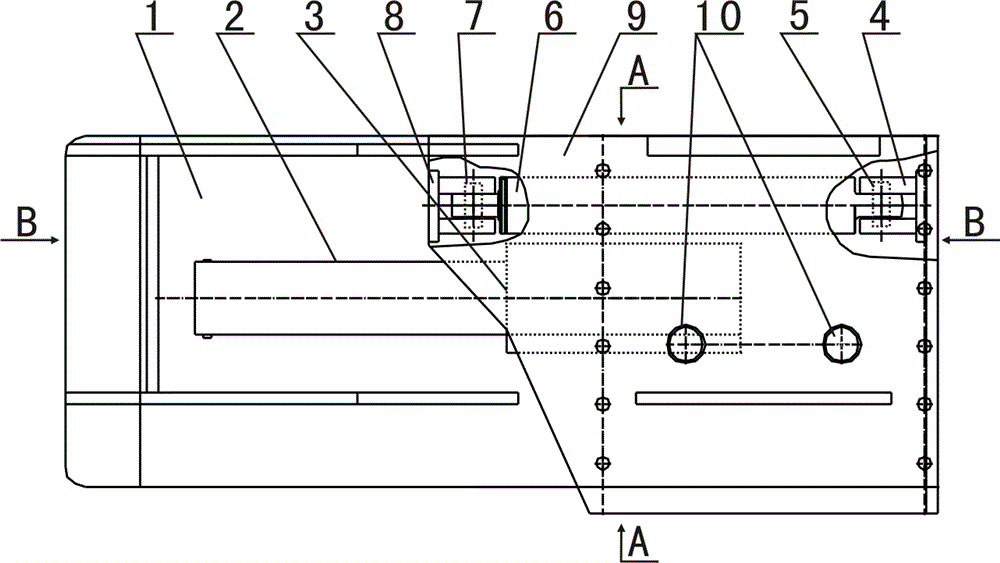
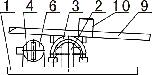
[0021] combined with Figure 1~2 The head and tail pushing device of the scraper machine, the device includes a lower base 1, a glideway 2, an upper slideway 3, a lower connecting seat 4, a jack 6, an upper connecting seat 8 and an upper pad 9; The upper surface of the lower base 1 is fixed with a glideway 2, and the tail end of the upper surface of the lower base 1 corresponding to the side of the glideway 2 is fixed with a lower connecting seat 4, that is, the lower connecting seat 4 is fixed on the upper surface of the lower base 1. tail end, and relatively located on one side of the glideway 2; the lower connecting seat 4 is connected to the tail end of the jack 6 through t...


PUM


Abstract

The invention relates to a scraper conveyor head and tail traction device in the field of transportation equipment for coal mines. The device comprises a lower base, a lower sliding way, an upper sliding way, a lower connecting seat, a jack, an upper connecting seat and an upper cushion frame, wherein the lower sliding way and the lower connecting seat are fixedly arranged on the upper surface of the lower base, the lower connecting seat is connected with the tail end of the jack, the head end of the jack is connected with the upper connecting seat, the upper connecting seat is fixedly connected with the head end of the bottom surface of the upper cushion frame, the middle part of the bottom surface of the upper cushion frame is fixedly connected with the top part of the upper sliding way, the upper sliding way and the lower sliding way are correspondingly and slidably fit, and stabilizing nails are arranged on the top surface of the upper cushion frame. The device can quickly and efficiency realize the goal of traction of a scraper conveyer head and tail with the advancing of a working face.

Description

[0001] 【Technical field】 [0002] The invention relates to the field of transportation equipment for coal mines, in particular to a moving device for moving the nose and tail of a scraper machine on a coal mine working face. [0003] 【Background technique】 [0004] As we all know, the scraper machine is an important transportation equipment in the process of coal transportation. It is mainly used in the longwall coal mining face and undertakes the transportation task; the working principle of the scraper machine is to use the open chute as coal, gangue or materials, etc. The receiving part, the scraper is fixed on the chain to form the scraper chain, and this is used as the traction member. When the transmission part of the machine head is started, the sprocket on the shaft of the machine head is driven to rotate, so that the scraper chain circulates, thereby driving The material moves along the chute until it is unloaded at the head of the machine; however, in practical applic...

Claims


Application Information

Patent Timeline
Patent Type & Authority Patents(China)
IPC IPC(8): B65G21/10
Inventor 黄圣英徐亮杨林毕海泉史新恩孟清义
Owner 河南中车重型装备有限公司
Learn More