Automatic floating mechanism of screw locking machine

A floating mechanism and locking screw machine technology, which is applied in metal processing, metal processing equipment, manufacturing tools, etc., can solve the problems of machine structural parts and product damage, strong adverse reaction force, etc.

Active Publication Date: 2014-12-24
六壹八技术(深圳)有限公司
View PDF5 Cites 9 Cited by
  • Summary
  • Abstract
  • Description
  • Claims
  • Application Information

AI Technical Summary

Problems solved by technology

[0005] Due to the inconsistency between the product position and the coordinate position and the abnormality of the screw incoming material, the strong adverse reaction force generated when the screw is forcibly locked will damage the machine structure and products.

Method used


Image

  • Automatic floating mechanism of screw locking machine
  • Automatic floating mechanism of screw locking machine
  • Automatic floating mechanism of screw locking machine

Examples


Embodiment Construction

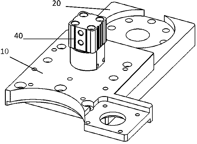
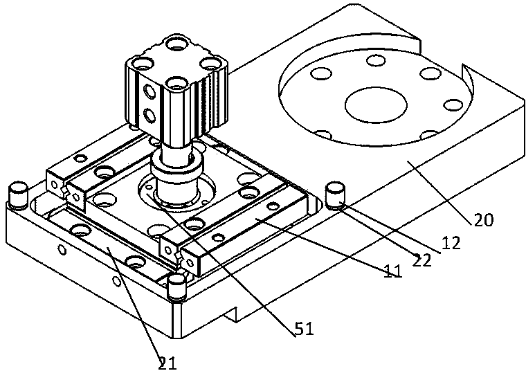
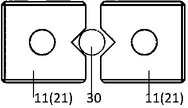
[0019] Example Figures 1 to 5 shown. A self-floating mechanism for locking screw machines, including a floating plate, a middle plate and a lower cover plate, an X-direction ball guide rail 11 is also included between the floating plate and the middle plate, and the X-direction ball guide rail 11 is connected to the floating There is also a Y-direction ball guide rail 21 between the lower cover board and the middle board, and the Y-direction ball guide rail 21 connects the lower cover board and the middle board. The X-direction ball guide 11 enables relative movement between the floating plate and the middle plate along the X-axis direction. The Y-direction ball guide rail 21 enables relative movement between the middle plate 50 and the lower cover plate 20 along the Y-axis direction. Therefore, the floating plate 10 can float in the horizontal direction relative to the lower cover plate 20 after being stressed.

[0020] The rail length is shorter than the slot that accomm...


PUM


Abstract

The invention relates to the field of automatic screw machines, in particular to an automatic floating mechanism of a screw locking machine. The automatic floating mechanism comprises a floating plate (10), a middle plate (50) and a lower cover plate (20). X-direction ball guide rails (11) are further arranged between the floating plate (10) and the middle plate (50) and are connected with the floating plate (10) and the middle plate (50), and Y-direction ball guide rails (21) are further arranged between the lower cover plate (20) and the middle plate (50) and are connected with the lower cover plate (20) and the middle plate (50). The automatic floating mechanism has the advantages that screw tightening positions can be automatically adjusted by the aid of the automatic floating mechanism; unstable locking and oblique locking can be reduced; the automatic screw locking machine can be prevented from being damaged under the effect of external force due to non-correspondence between screw holes and screws, eccentricity of the screw holes and the screws can be automatically compensated, and the screw holes and the screws can be automatically aligned with one another.

Description

technical field [0001] The invention relates to the field of automatic screw machines, in particular to a self-floating mechanism for locking screw machines. Background technique [0002] The existing automatic screw locking equipment adopts Cartesian coordinates or multi-joint robots to automatically lock screws according to the input product coordinate data information. These automatic locking screw mechanisms or robots all work in a relatively fixed manner. Screws can only be screwed to fixed positions. Such an organization has the following disadvantages. [0003] When the actual position due to product processing errors, deformation, displacement, etc. does not match the coordinate position stored by the device, the screw will not lock in, slip teeth, destructively lock in, and damage the product. [0004] When the screw is not concentric or shaped due to screw processing, it will cause floating lock and oblique lock. [0005] Due to the inconsistency between the pr...

Claims


Application Information

Patent Timeline
IPC IPC(8): B23P19/06B23P19/10
CPCB23P19/06B23P19/10
Inventor 夏正磊
Owner 六壹八技术(深圳)有限公司
Why Eureka
Try Eureka