
Special electric welding machine for welding stainless steel water tank

A technology of stainless steel, electric welding machine

Inactive Publication Date: 2014-12-24
湖州佳士不锈钢制品有限公司
View PDF9 Cites 2 Cited by
  • Summary
  • Abstract
  • Description
  • Claims
  • Application Information

AI Technical Summary

Problems solved by technology

[0008] 1. During welding, the panel and the tank cannot be positioned accurately. Once the positioning is not accurate, the panel and the tank will not be effectively connected together, cracks will appear during use, and the service life of the stainless steel sink after welding is short
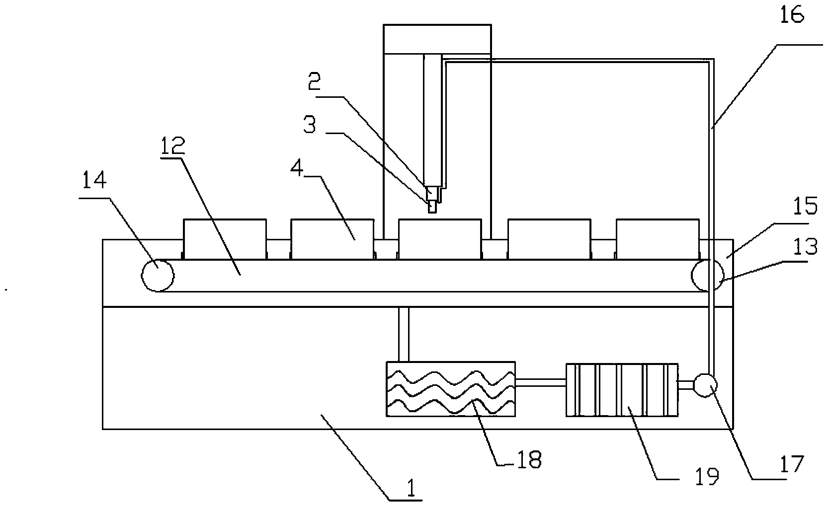
[0009] 2. Due to the high welding temperature during welding, it is necessary to continuously cool the weld seam and the welding head. However, the above-mentioned existing resistance welding machine does not have a cooling system, which causes the welding head to soften due to heat and the weld seam unevenness, unevenness
[0010] 3. Workers need to put a single panel and tank together for welding when welding, and then change to another one for welding after welding. When changing the panel and tank, the welding machine needs to be stopped, which reduces the welding efficiency

Method used


Image

  • Special electric welding machine for welding stainless steel water tank
  • Special electric welding machine for welding stainless steel water tank
  • Special electric welding machine for welding stainless steel water tank

Examples


Embodiment 1

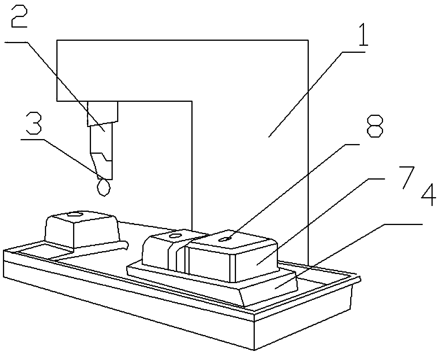
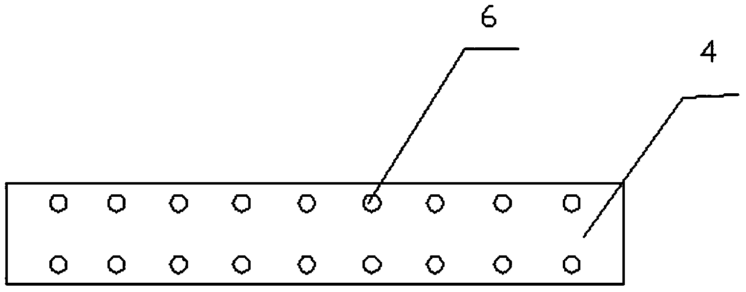
[0038] This embodiment includes a frame 1, a welding head connecting frame 2 and a welding head 3, and the welding head 3 is connected to the frame 1 through the welding head connecting frame 2, and also includes a workbench 4 and a positioning part 5, and the workbench 4 is fixed on the frame 1, the workbench 4 is located under the welding head 3, a plurality of positioning holes 6 are arranged on the workbench 4, the positioning part 5 is installed on the positioning holes 6 by bolts, and the positioning part 5 has at least two indivual. In this embodiment, a workbench and a positioning piece are added to the existing welding machine. The role of the positioning piece is to accurately position the stainless steel water tank body and panel to prevent the stainless steel tank body and panel from shifting, causing poor welding quality. When welding, put the panel on the workbench, position the tank body with a positioning piece, fix the tank body, and the tank body will not sha...

Embodiment 2

[0045] This embodiment includes a frame 1, a welding head connecting frame 2 and a welding head 3, and the welding head 3 is connected to the frame 1 through the welding head connecting frame 2, and also includes a workbench 4 and a positioning part 5, and the workbench 4 is fixed on the frame 1, the workbench 4 is located under the welding head 3, a plurality of positioning holes 6 are arranged on the workbench 4, the positioning part 5 is installed on the positioning holes 6 by bolts, and the positioning part 5 has at least two indivual.

[0046] The positioning part 5 of this embodiment is a cylindrical positioning part, which is fixed on the positioning hole 6 by bolts, and the diameter of the cylindrical positioning part matches the water leakage hole of the stainless steel tank body 7. The positioning part 5 of this embodiment is a cylindrical positioning part. When welding, the cylindrical positioning part is passed through the leakage hole 8 of the stainless steel wate...

Embodiment 3

[0052] This embodiment includes a frame 1, a welding head connecting frame 2 and a welding head 3, and the welding head 3 is connected to the frame 1 through the welding head connecting frame 2, and also includes a workbench 4 and a positioning part 5, and the workbench 4 is fixed on the frame 1, the workbench 4 is located under the welding head 3, a plurality of positioning holes 6 are arranged on the workbench 4, the positioning part 5 is installed on the positioning holes 6 by bolts, and the positioning part 5 has at least two indivual.

[0053] The positioning part 5 of this embodiment is an "L" shaped positioning part, including a mounting part 9 and a positioning part 10. The mounting part 9 is provided with a mounting hole 11. The positioning part 10 is perpendicular to the mounting part 9, and the bolt passes through the The mounting hole 11 and the positioning hole 6 fix the positioning member 5 on the workbench 4 .

[0054] There can be one or more workbenches in th...


PUM


Abstract

The invention discloses a special electric welding machine for welding a stainless steel water tank. The special electric welding machine comprises a rack, a welding head connecting rack and a welding head, wherein the welding head is connected to the rack by virtue of the welding head connecting rack; the special electric welding machine further comprises a workbench and at least two locating pieces; the workbench is fixedly arranged on the rack and positioned below the welding head; the workbench is provided with multiple locating holes; the locating pieces are arranged in the locating holes. As actual conditions during stainless steel water tank welding are fully considered, the special electric welding machine is accurate in locating and free from welding deviation.

Description

technical field [0001] The invention relates to an electric welding machine, in particular to an electric welding machine for welding a stainless steel water tank body and a panel. Background technique [0002] In the field of stainless steel water tank production, the commonly used method is to produce the tank body and panel of the stainless steel tank, and then weld the panel and the tank body with a welding machine. The commonly used electric welding machine is a resistance welding machine. The principle of the resistance welding machine is to compress the workpiece to be welded between the two electrodes, and apply current, and use the resistance heating effect generated by the current flowing through the contact surface of the workpiece and the adjacent area to heat it to a molten or plastic state, so that it forms a metal A combined machine. The resistance welding machine is divided into: single-phase AC resistance welding machine, intermediate frequency inverter wel...

Claims


Application Information

Patent Timeline
IPC IPC(8): B23K11/36B23K37/04
CPCB23K31/02B23K37/00B23K37/003B23K37/0435B23K2103/04
Inventor 潘利敏
Owner 湖州佳士不锈钢制品有限公司
Learn More