Angle adjusting and locking device of rotary plate

A locking device and angle adjustment technology, which is applied in metal processing equipment, metal rolling, manufacturing tools, etc., can solve the problems of occupying a large space, long adjustment time, and change of the corner of the loose bar roller, etc., and achieves a compact structure of the device, The effect of low manufacturing cost and flexible adjustment

Active Publication Date: 2014-12-24
CERI TECH +1
View PDF7 Cites 3 Cited by
  • Summary
  • Abstract
  • Description
  • Claims
  • Application Information

AI Technical Summary

Problems solved by technology

[0004] At present, the loose rod roller angle adjustment device used on the loose rod machine mostly adopts nut screw (worm gear) adjustment or electric pull rod adjustment, and the adjustment speed is slow. Poor adjustment accuracy and takes up a lot of space
[0005] The existing common corner locking device is to directly adopt the pulling force of the hydraulic cylinder (such as: the application number is 200620030320.2 "Slant Roll Leveler Corner Plane Locking Mechanism") or directly use the method of bolt connection to compress, and its disadvantages are: Since the friction force generated by the direct use of the oil cylinder tension between the two planes will be affected by the change of oil pressure, there will be a small displacement change, which will cause a change in the rotation angle of the loose rod roller; in addition, the use of hydraulic locking has high manufacturing and maintenance costs.
The method of directly tightening with bolt jackscrews not only takes a long time to adjust, but also the jackscrew bolts cannot rotate with the turntable on which the loose bar roller is installed after the roll angle is adjusted, resulting in only point and line contact, and the locking effect is poor

Method used


Image

  • Angle adjusting and locking device of rotary plate
  • Angle adjusting and locking device of rotary plate
  • Angle adjusting and locking device of rotary plate

Examples


Embodiment Construction

[0021] In order to have a clearer understanding of the technical features, purposes and effects of the present invention, the specific implementation manners of the present invention will now be described with reference to the accompanying drawings.

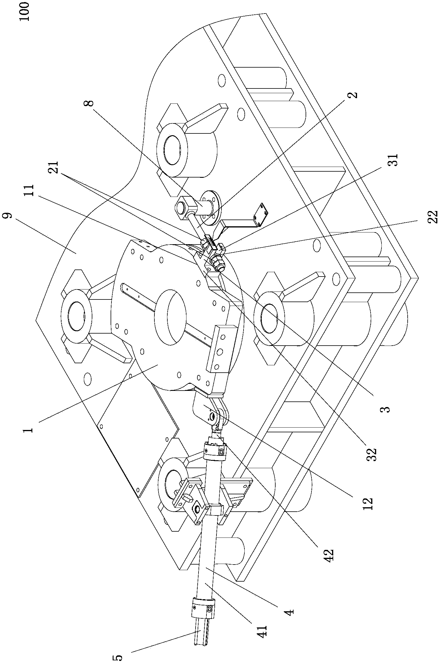
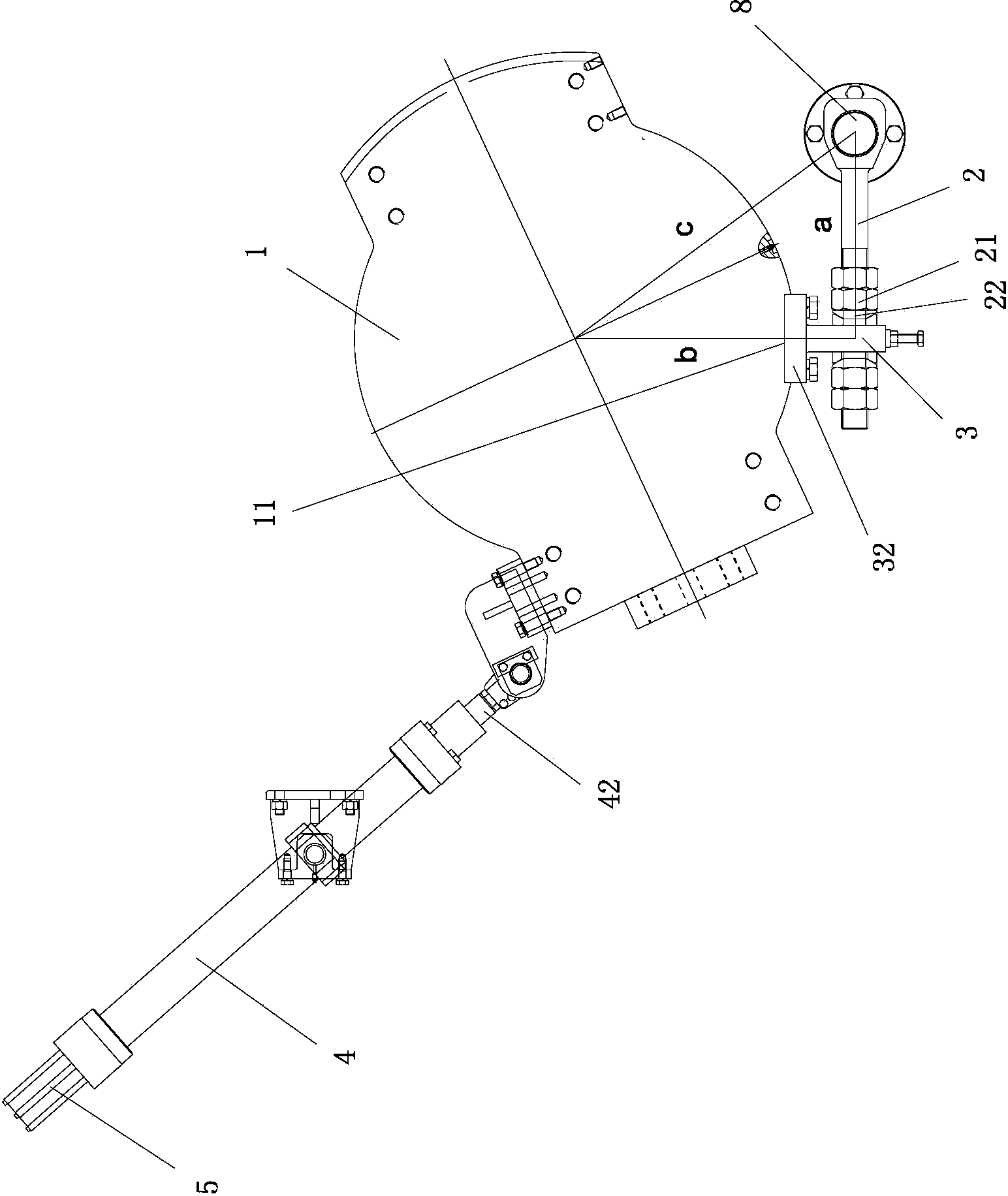
[0022] Such as figure 1 , figure 2 As shown, the present invention proposes a turntable angle adjustment and locking device 100, the turntable angle adjustment and locking device 100 includes a base 9, the base 9 is provided with a central hole 91; the bottom of a turntable 1 is rotatably arranged on In the central hole 91 of the base; the base 9 adjacent to the turntable 1 side is provided with a vertically arranged pin shaft seat 8 (that is: the axial direction of the pin shaft seat 8 is parallel to the axial direction of the central hole 91 of the base 9), a One end of the screw rod 2 is hinged to the pin seat 8; the side wall of the turntable 1 is fixed with a projection 3 extending along the radial direction of the turntab...


PUM


Abstract

The invention provides an angle adjusting and locking device of a rotary plate. The device comprises a base, wherein a central hole is formed in the base; the rotary plate is arranged in the central hole of the base in a rotating way; a pin shaft base which is vertically arranged is arranged on the base adjacent to one side of the rotary plate, and one end of a screw rod is hinged with the pin shaft base; a bump which is arranged along the radial direction of the rotary plate in an extending way is fixedly arranged on the side wall of the rotary plate, a U-shaped slot with an opening facing the external end of the bump is arranged on the bump, the screw rod is arranged in the U-shaped slot in a penetrating way, and double nuts for fastening the bump are respectively formed on the screw rods at two sides of the bump; a corner oil cylinder for driving the rotary plate to rotate is connected to the side wall positioned at the other side of the rotary plate, the cylinder body of the corner oil cylinder is hinged to the base, and a piston rod of the corner oil cylinder is hinged to the side wall of the rotary plate; a displacement sensor is arranged on the corner oil cylinder. The device is compact in structure, reliable to be locked, flexible to adjust, simple and convenient to maintain; the rotation angle of the rotary plate is accurately controlled; the operation of adjusting a work angle of the rotary plate in an adjusting range can be satisfied.

Description

technical field [0001] The invention relates to a roll inclination angle adjustment and locking device of a bar loosening machine, in particular to a turntable angle adjustment and locking device. Background technique [0002] The skewed roll loosening machine is mainly used in the seamless steel pipe jacking production line, and is widely used in the metallurgical industry. The steel pipe held tightly on the mandrel is rolled by the loosening machine to create a gap between the steel pipe and the mandrel. [0003] The inclination angle of the roll of the inclined roll loosening machine needs to be adjusted according to the diameter of the rolled pipe, and the adjustment accuracy is high. During the rolling process, the roll is subjected to a rotational force along the circumferential direction, and the lock can only work after the rotation angle is adjusted. [0004] At present, the loose rod roller angle adjustment device used on the loose rod machine mostly adopts nut s...

Claims


Application Information

Patent Timeline
Patent Type & Authority Applications(China)
IPC IPC(8): B21B25/00
Inventor 李慧斌胡晓军安宏生贾庆春高学文刘秀军魏春颖
Owner CERI TECH
Why Eureka
Try Eureka