
Desulfurization side filtration method in propylene carbonate decarbonization process

A propylene carbonate and decarburization technology, applied in separation methods, chemical instruments and methods, filtration circuits, etc., can solve problems such as sulfur blockage, and achieve the effects of easy cleaning, obvious desulfurization effect, and convenient operation

Inactive Publication Date: 2014-12-24
ANHUI JINGHE IND
View PDF2 Cites 2 Cited by
  • Summary
  • Abstract
  • Description
  • Claims
  • Application Information

AI Technical Summary

Problems solved by technology

[0003] The purpose of the present invention is to solve the sulfur clogging problem in the propylene carbonate decarburization process, and provide a desulfurization bypass filter method in the propylene carbonate decarburization process

Method used


Image

  • Desulfurization side filtration method in propylene carbonate decarbonization process
  • Desulfurization side filtration method in propylene carbonate decarbonization process

Examples


Embodiment 1

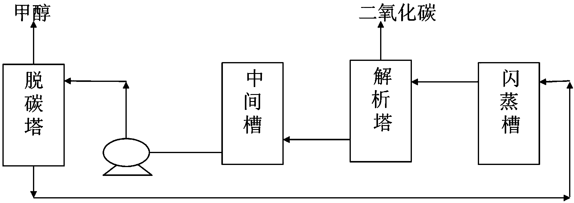
[0010] Such as figure 1 As shown, the CO in the shift gas 2 In the decarbonization tower and reverse absorption with propylene carbonate solution, the purified gas goes to the methanol production unit to absorb CO 2 After the solution is desorbed by the flash tank and the desorption tower to remove CO 2 The gas and solution are regenerated into the middle tank, and then pumped into the decarbonization tower through the decarbonization pump, so that the cycle is continuous;

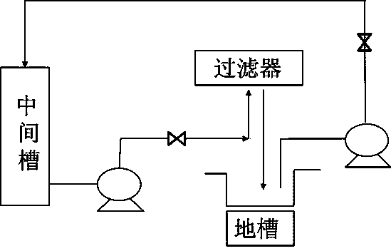
[0011] Such as figure 2 As shown, the liquid in the middle tank is 6m 3 The flow rate of / h is pumped into the XMY-800 filter, and the filtered liquid enters the trough, and the liquid in the trough is 6m 3 The flow rate of / h circulates back to the middle tank.


PUM


Abstract

The invention belongs to the technical field of synthetic ammonia production and relates to a desulfurization side filtration method in a propylene carbonate decarbonization process. The method comprises the following steps: arranging a geosyncline between an intermediate tank and a decarbonization tower, filtering part of liquid in the intermediate tank, and cyclically returning filter liquor after filtration to the intermediate tank to continuously take part in a reaction process. According to the method, the sulfur content of the mother liquid in the intermediate tank can be effectively reduced.

Description

technical field [0001] The invention belongs to the technical field of synthetic ammonia production, and relates to a desulfurization side filtration method in a propylene carbonate decarburization process. Background technique [0002] The propylene carbonate decarburization process is a physical absorption method, which has the advantages of low energy consumption, high stability and low corrosion. This method is applied to the decarburization process of ammonia-synthesized shift gas. Because of its simple process and obvious energy-saving effect, it has been popularized and applied in many synthetic aminoglycol manufacturers. At present, the main process of the propylene carbonate decarburization process is: to change the CO in the gas 2 In the decarbonization tower and reverse absorption with propylene carbonate solution, the purified gas goes to the methanol production unit to absorb CO 2 After the solution is desorbed by the flash tank and the desorption tower to rem...

Claims


Application Information

Patent Timeline
Patent Type & Authority Applications(China)
IPC IPC(8): B01D53/14B01D36/04
CPCY02C20/40
Inventor 孙彩军程晓军
Owner ANHUI JINGHE IND
Learn More