Pusher guidewire

A technology of guide wire and pressure, applied in the direction of guide wire, stent, etc., can solve the problems of stent damage to the inner wall of the blood vessel and stent recovery.

Inactive Publication Date: 2014-12-24
PENTAS INC
View PDF6 Cites 3 Cited by
  • Summary
  • Abstract
  • Description
  • Claims
  • Application Information

AI Technical Summary

Problems solved by technology

Since the self-expanding stent cannot recover the stent that has been expanded at the front end of the catheter into the catheter, the expanded stent may damage the inner wall of the normal blood vessel when the doctor retrieves the stent

Method used


Image

  • Pusher guidewire
  • Pusher guidewire
  • Pusher guidewire

Examples


Embodiment Construction

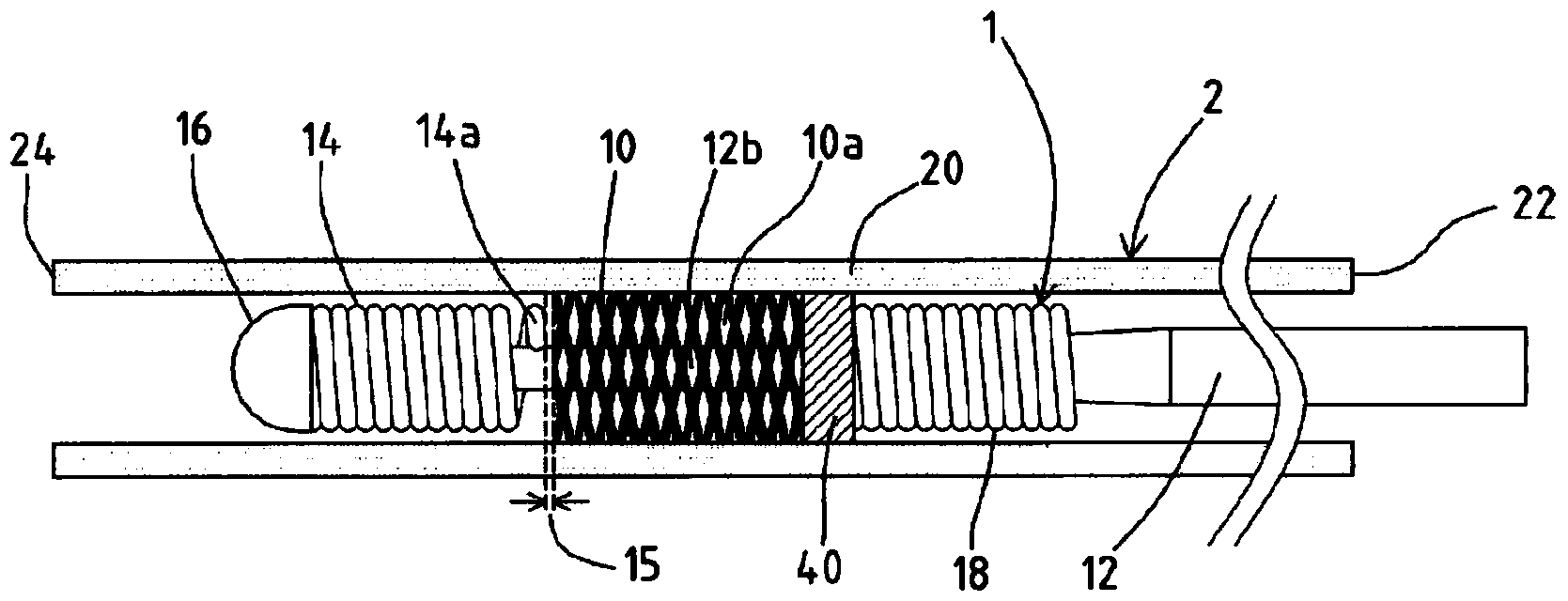
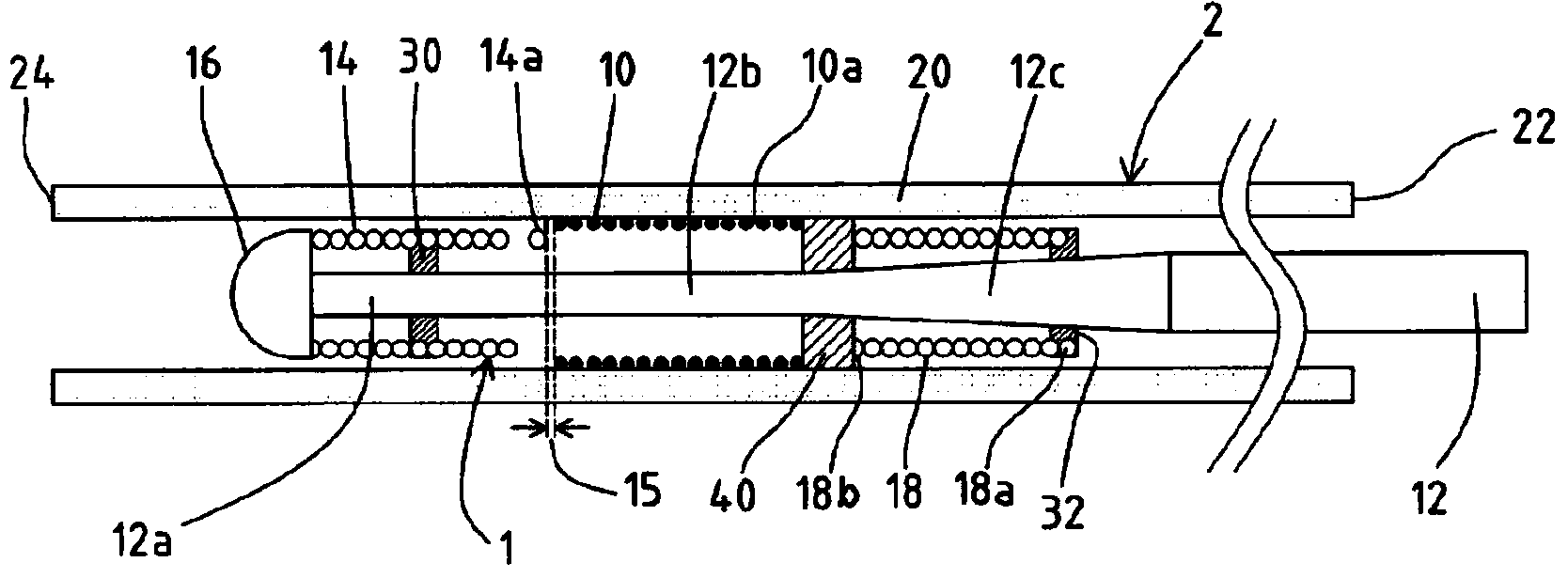
[0052]First, the pressure wire 1 according to the present embodiment will be described with reference to FIGS. 1(A) to 5(B). In Fig. 1(A) to Fig. 5(B), the left side is the front end side (distal side) inserted into the body, and the right side is the rear end side (proximal side, proximal side) where the operator such as a doctor operates. side). Figure 1(B) is a cross-sectional view of Figure 1(A); Figure 2(B) is a cross-sectional view of Figure 2(A); Figure 3(B) is a cross-sectional view of Figure 3(A); Figure 4(B) is a sectional view of FIG. 4(A); FIG. 5(B) is a sectional view of FIG. 5(A).

[0053] First, as shown in FIG. 1(A) and FIG. 1(B), the pressure guide wire 1 is used to deliver the stent 10 to the target site. The pressure guide wire 1 includes: a central shaft 12; a front coil body 14, which is wound On the outer periphery of the first front end part 12a of the central shaft 12; the front end head 16, which connects the front end of the central shaft 12 and the...


PUM


Abstract

It is an object of the present invention to provide a pusher guidewire in which a coil has a free rear end that is not fixed to a core shaft, thereby allowing a stent that has been partially deployed from the front end of a catheter to be retrieved into the catheter. In a pusher guidewire (1, 1a, 1b, 1c, 1d), a front end coil (14, 64, 74, 84, 94) has a free rear end (14a, 64a, 74a, 84a, 94a) that is not fixed to a first front end portion (12a) of a core shaft (12). By pulling the core shaft toward the rear end, the free rear end catches a gap (10a) of a partially-deployed stent (10). By rotating the core shaft in this state, a front end portion (11) of the stent deployed from a front end opening (24) of a catheter (2) is wrapped around the outer circumference of the front end coil. Further pulling the core shaft toward the rear end with the wrapped stent retrieves the partially-deployed stent into the catheter, thereby preventing the stent from damaging the inner wall of a normal blood vessel.

Description

technical field [0001] The invention relates to a pressure guide wire used for delivering a stent accommodated in a catheter to a target site. Background technique [0002] A stent is a medical device used to support the lumen of a blood vessel or digestive organ. When in use, the blood vessel or digestive organ is first expanded with a balloon catheter, etc., and then the stent is inserted to prevent the blood vessel or digestive organ from narrowing again. Stents are roughly classified into two types, one is a balloon-expandable stent that is expanded with a balloon catheter or the like, and the other is a self-expandable stent that expands naturally by itself. Since the self-expanding stent is not easy to deform after being subjected to external force, it has been widely used recently. [0003] Regarding the method of delivering the self-expanding stent to the target site, there is a known technique: the stent is arranged on the outer periphery of the pressure guide wire...

Claims


Application Information

Patent Timeline
Patent Type & Authority Applications(China)
IPC IPC(8): A61M25/09
CPCA61F2/966A61F2002/9665A61F2002/9528A61F2002/9534A61F2/95A61M2025/09175A61M2025/09083
Inventor 西岸诚
Owner PENTAS INC
Why Eureka
Try Eureka