Wheeled Structures for Harvesters
A technology for harvesters and pulleys, applied to harvesters, belts/chains/gears, applications, etc., can solve problems such as troubles, and achieve the effect of convenient adjustment
- Summary
- Abstract
- Description
- Claims
- Application Information
AI Technical Summary
Problems solved by technology
Method used
Image
Examples
Embodiment 1
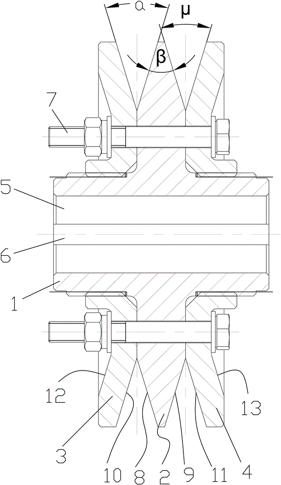
[0022] Embodiment 1, see attached figure 1 The fan pulley structure for the harvester includes a transmission shaft 1, an intermediate wheel 2 fixed on the transmission shaft 1, a left side wheel 3 that is installed on the intermediate wheel 2 and can move axially, and is installed On the middle wheel 2 and the right side wheel 4 capable of axial movement, the axial through hole 5 arranged on the transmission shaft 1, the connecting mechanism 6 arranged in the axial through hole 5 and the The adjustment connecting mechanism 7 that described left side wheel 3, right side wheel 4 and middle wheel 2 are connected; Said middle wheel 2 is provided with left side plane and is positioned at described left side plane radial outside The left annulus 8 that intersects and inclines to the direction of the right wheel 4, the right plane, and the right annulus 9 that intersects the right plane radially outside the right plane and inclines to the direction of the left wheel 3, so The exten...
Embodiment 2
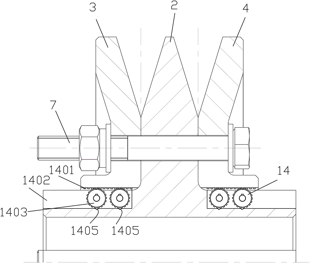
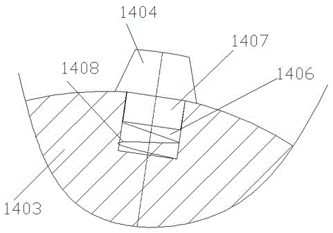
[0023] Embodiment 2, see attached figure 2 , 3 ; In this embodiment, the left wheel 3 and the right wheel 4 are sleeved on the transmission shaft 1, and can rotate and slide axially on the transmission shaft. The left wheel 3 and the transmission A locking mechanism 14 is provided between the shafts 1 and between the right side wheel 4 and the transmission shaft 1. When the left side wheel 3 and the right side wheel 4 move on the transmission shaft 1 at a speed exceeding Lock the left side wheel 3 and the right side wheel 4 at a predetermined value; the locking mechanism 14 includes and is arranged on the left side wheel 3 and the right side wheel 4. The axial groove 1402 on the transmission shaft 1, the roller 1403 hinged in the axial groove 1402, the teeth 1404 arranged on the roller 1403 and meshed with the rack 1401 and arranged on the shaft To the slot 1405 at the bottom of the groove 1402, the outer circumference of the roller 1403 is provided with an opening guide gr...
PUM
 Abstract
Description
Claims
Application Information
 - R&D
- Intellectual Property
- Life Sciences
- Materials
- Tech Scout
- Unparalleled Data Quality
- Higher Quality Content
- 60% Fewer Hallucinations
Browse by: Latest US Patents, China's latest patents, Technical Efficacy Thesaurus, Application Domain, Technology Topic, Popular Technical Reports.
© 2025 PatSnap. All rights reserved.Legal|Privacy policy|Modern Slavery Act Transparency Statement|Sitemap|About US| Contact US: help@patsnap.com


