
A Calculation Method for Rotor Position of Permanent Magnet Motor

A technology of permanent magnet motor and calculation method, which is applied in the direction of controlling generator, motor generator control, controlling electromechanical transmission device, etc. The effect of small error in calculation results

Active Publication Date: 2017-01-18
SOUTHEAST UNIV
View PDF3 Cites 0 Cited by
  • Summary
  • Abstract
  • Description
  • Claims
  • Application Information

AI Technical Summary

Problems solved by technology

After the installation position of the photoelectric encoder and the motor shaft changes, it needs to be re-measured, which is not only a waste of time, but also has low versatility. It is necessary to modify the corresponding angle difference for different control systems.

Method used


Image

  • A Calculation Method for Rotor Position of Permanent Magnet Motor
  • A Calculation Method for Rotor Position of Permanent Magnet Motor
  • A Calculation Method for Rotor Position of Permanent Magnet Motor

Examples


Embodiment Construction

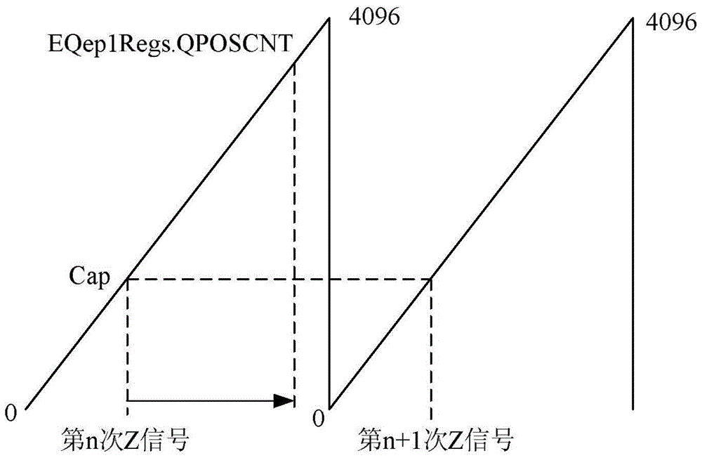
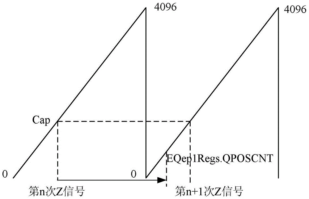
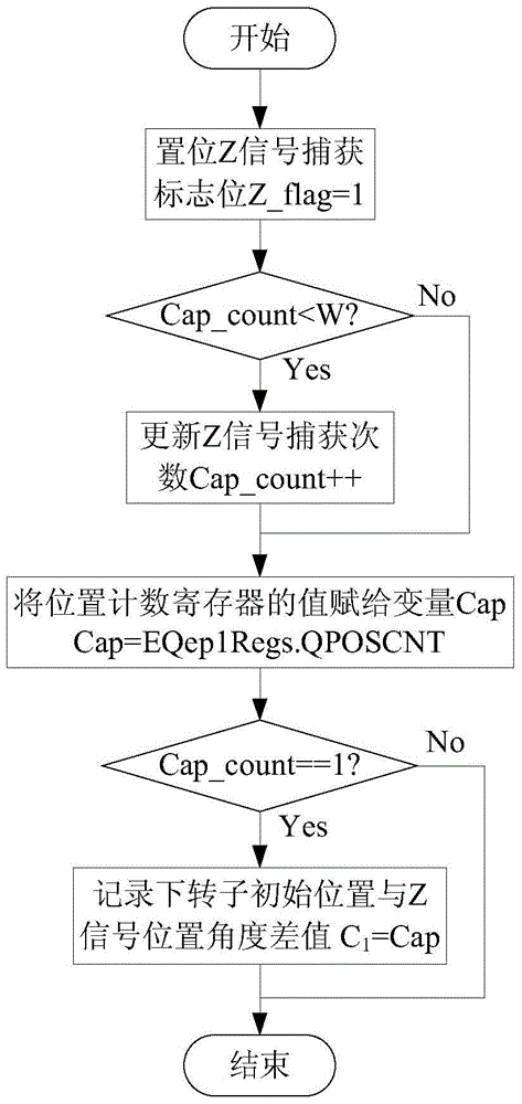
[0026] In the method for calculating the rotor position of the permanent magnet motor of the present invention, the controller captures the Z signal that appears in each circle of the incremental photoelectric encoder, so as to realize the acquisition of the angle difference between the initial position of the permanent magnet motor rotor and the Z signal position of the photoelectric encoder. Limit the error of the A and B pulse signal count values ​​used to calculate the rotor angle within one revolution. Specifically, the realization of the above-mentioned method includes the following steps (the number of pulses of one revolution of the incremental photoelectric encoder is M, and there is no other way to carry out frequency multiplication counting of the A and B orthogonal pulse signals, that is, the number of times the photoelectric encoder makes one revolution The pulse count value is M, and the corresponding mechanical angle radian value is 2π. The maximum count value of...


PUM


Abstract

The invention provides a permanent magnet motor rotor position calculation method and aims to limit a count error of orthogonal pulse signals A and B, used in calculating a rotator position, within a circle through a Z pulse signal of an incremental photoelectric encoder. The method is characterized in that after the incremental photoelectric encoder is installed on a rotating shaft of a motor, an angular difference between an initial position of a motor rotor and the position of the Z pulse signal of the incremental photoelectric encoder needs no additional measurement and is determined via a value of a position counting register of a controller when the controller acquires the Z pulse signal for the first time; the position counting register of the controller is unaffected when the Z pulse signal is used to eliminate the rotor position angular error; the count error of the orthogonal pulse signals A and B used in calculating the rotor position angle, is limited within one circle. According to one-circle pulse counts of the incremental photoelectric encoder, the pulse counts correspond to the rotor position angle, and the corresponding motor rotor angle can be obtained after the counts of the orthogonal pulse signals A and B are obtained.

Description

technical field [0001] The invention relates to the field of calculation of the rotor position of a permanent magnet motor, in particular to a method for reducing the calculation error of the rotor position by using the Z signal of an incremental photoelectric encoder. Background technique [0002] In the permanent magnet motor vector control system, the rotor position angle value is a necessary condition for vector control decoupling, and the accuracy of rotor position detection directly affects the control effect of vector control. At present, the methods used to detect the rotor position of the permanent magnet synchronous motor are generally divided into two categories: the position detection method with a position sensor and the position detection method without a position sensor. The position sensorless detection method mainly calculates the rotor position by measuring the stator side current and terminal voltage of the motor. Compared with the position detection metho...

Claims


Application Information

Patent Timeline
Patent Type & Authority Patents(China)
IPC IPC(8): H02P21/18
Inventor 程明王亚王伟
Owner SOUTHEAST UNIV
Learn More