
Method and device for planning distributed type power supply system

A power supply system, distributed technology, applied in the direction of circuit devices, electrical components, AC network circuits, etc., can solve the problem of reducing the carbon footprint of terminal electricity consumption, and achieve the effect of reducing carbon footprint and optimizing solution accuracy

Inactive Publication Date: 2014-12-17
NORTH CHINA ELECTRIC POWER UNIV (BAODING)
View PDF2 Cites 11 Cited by
  • Summary
  • Abstract
  • Description
  • Claims
  • Application Information

AI Technical Summary

Problems solved by technology

[0005] However, the above-mentioned planning methods cannot fully achieve the basic goal of effectively reducing the carbon footprint of end-use electricity

Method used


Image

  • Method and device for planning distributed type power supply system
  • Method and device for planning distributed type power supply system
  • Method and device for planning distributed type power supply system

Examples


Embodiment Construction

[0047] Exemplary embodiments of the present disclosure will be described in more detail below with reference to the accompanying drawings. Although exemplary embodiments of the present disclosure are shown in the drawings, it should be understood that the present disclosure may be embodied in various forms and should not be limited to the embodiments set forth herein. Rather, these embodiments are provided for more thorough understanding of the present disclosure and to fully convey the scope of the present disclosure to those skilled in the art.

[0048] After analyzing the existing planning methods of distributed power supply systems, the inventors of the present application found that the reasons why they cannot fully realize the basic goal of effectively reducing the carbon footprint of terminal power consumption are as follows:

[0049] 1) Ignoring the implied carbon emissions caused by the use of system equipment (feeders, DG), that is, the indirect carbon emissions caus...


PUM


Abstract

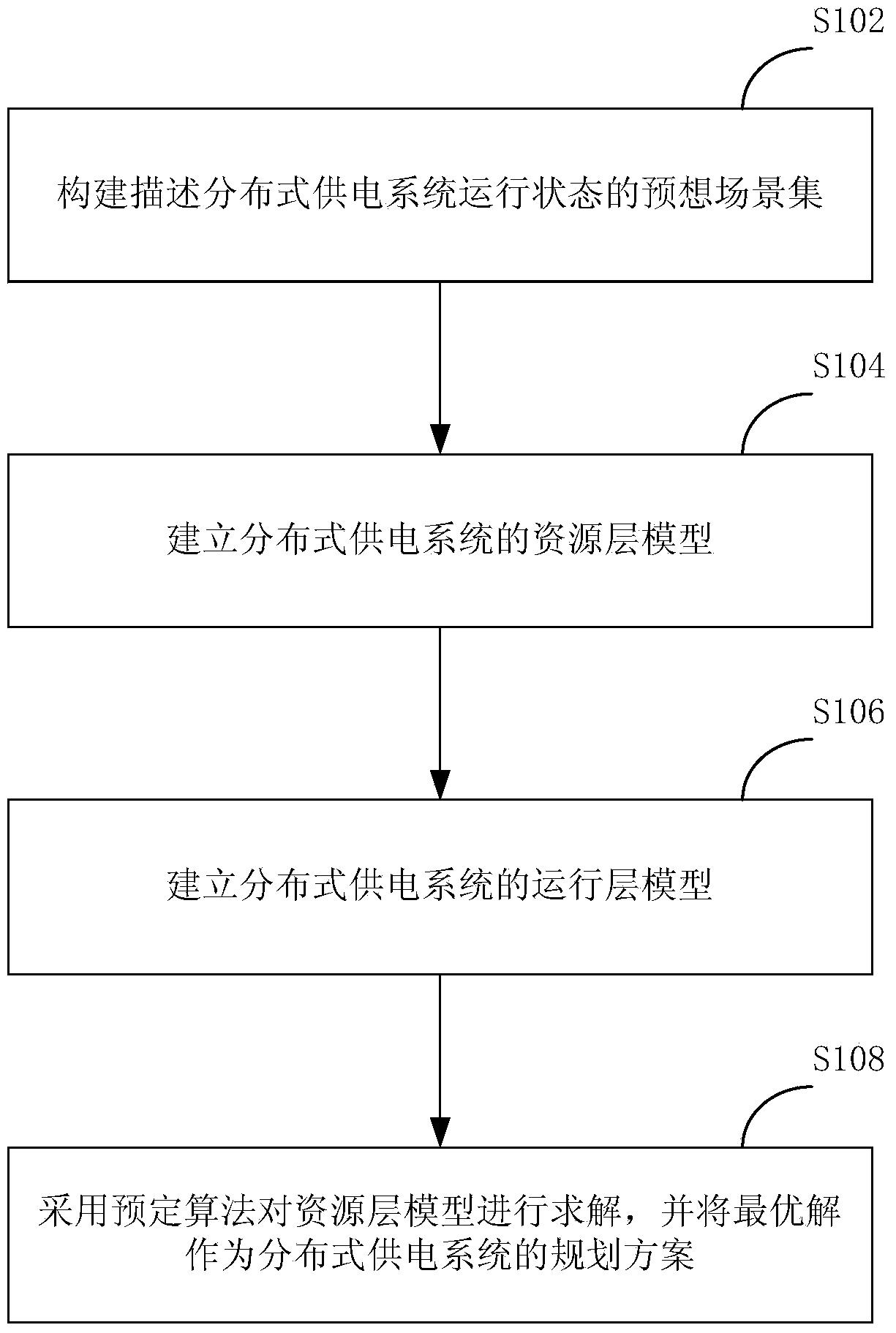
The invention discloses a method and device for planning a distributed type power supply system. The planning method comprises the steps of establishing a resource layer model of the distributed type power supply system, wherein control variables of the resource layer model comprise a first vector for representing a system network topology and feeder linetype and a second vector for representing the installing positions of renewable energy generation units in the system and the configuration number, an object function of the resource layer model is min F=(DC+OC) / H, wherein DC represents hidden carbon emission, OC represents power generation carbon emission, and H represents a power consumption prediction value; establishing an operation layer model of the distributed type power supply system, control variables of the operation layer model comprise a third vector for representing renewable energy generation unit call power of the system during the running and calling electric energy from a superior power grid, wherein an objection function of the operation layer model is min f=OC / epsilon, wherein epsilon is a variation factor; adopting a predetermined algorithm to solve the resource layer model, obtaining optimal solutions of the first vector and the second vector, and adopting the optimal solutions to serve as a planning scheme for the distributed type power supply system. The method can effectively reduce carbon footprint of terminal power utilization.

Description

technical field [0001] The invention relates to power distribution optimization technology, in particular to a planning method and device for a distributed power supply system. Background technique [0002] Since the beginning of the 21st century, the shortage of fossil energy, climate change and environmental pollution have become common challenges facing the world. Therefore, improving the diversity of energy supply and reducing the dependence of end-use electricity on fossil energy, so as to minimize the carbon emissions caused by human activities, is an important issue facing the development of the electric power industry. [0003] Distributed Generation System (DGS) can realize local consumption of renewable energy such as wind and light by organically integrating various types of distributed generation (DG), power distribution network and terminal load. Therefore, it is an effective way to achieve the above goals. [0004] To establish a low-carbon DGS, the prerequis...

Claims


Application Information

Patent Timeline
Patent Type & Authority Applications(China)
IPC IPC(8): H02J3/00
Inventor 曾博欧阳邵杰张建华
Owner NORTH CHINA ELECTRIC POWER UNIV (BAODING)
Learn More