
Novel evaporative condenser

An evaporative condenser and condenser technology, which is applied in the direction of evaporator/condenser, refrigerator, refrigeration components, etc., can solve the problem of undetailed control scheme, increase of condensation heat exchange area outside the tube, uneven temperature of condenser, etc. problems, to achieve the effect of reducing water consumption and power consumption, improving heat exchange efficiency, and improving heat exchange capacity

Inactive Publication Date: 2014-12-17
SHANGHAI OCEAN UNIV
View PDF5 Cites 9 Cited by
  • Summary
  • Abstract
  • Description
  • Claims
  • Application Information

AI Technical Summary

Problems solved by technology

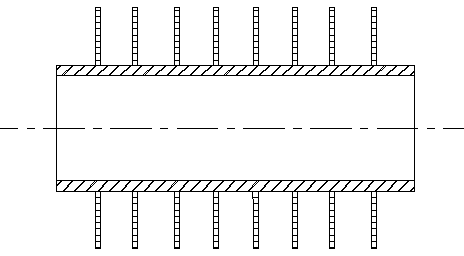
However, in the actual test, the patented evaporative condenser has no automatic temperature control function, and the outlet temperature of the process fluid fluctuates and is unstable, and there is a certain deviation from the ideal set temperature. This patent provides a new flat tube design with sleeves And add a multi-point temperature monitoring module to further increase the condensation heat transfer area outside the tube, and realize precise control of the outlet fluid temperature by automatically adjusting the inlet flow and other conditions
[0005] Jing Yuguo's patent (ZL201320303495.6): An energy-saving device for an evaporative condenser, which reflects the change in the internal load of the evaporative condenser by detecting the temperature of the air inlet and outlet, the temperature of the inlet and outlet of the cooled medium, and the temperature of the water tank. Technically solve the problem of uneven temperature inside the condenser, but fail to explain how to implement the control plan from a practical point of view, and the control plan is not detailed

Method used


Image

  • Novel evaporative condenser
  • Novel evaporative condenser
  • Novel evaporative condenser

Examples


Embodiment 1

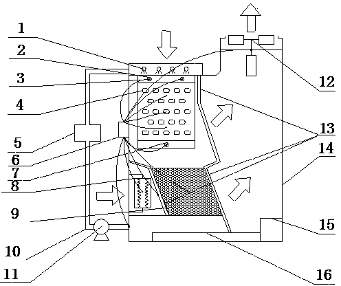
[0026] Embodiment 1: see attached figure 1 , the evaporative condenser consists of spray system 1, refrigerant inlet 2, temperature probe 3, flat round condenser coil with sleeve 4, electronic descaling instrument 5, multi-point temperature monitoring template 6, refrigerant outlet 7, Heating device 8, PVC radiating filler 9, water inlet pipe 10, circulating water pump 11, blower fan 12, water retaining plate 13, condenser metal shell 14, maintenance pedal 15, water collection tank 16 are formed.

[0027] The lower part of the nozzle of the sprinkler system is a condensing coil. There is a refrigerant inlet at the upper end of the condensing coil, and a refrigerant outlet at the lower end of the coil. After being heated by the heating device, the air at the air inlet is blown into the inner cavity of the condenser from the bottom of the condenser. There is a water baffle on the side of the condenser coil and PVC heat dissipation filler. The bottom of the condenser is a water c...


PUM


Abstract

The invention relates to a novel evaporative condenser. The device consists of a spraying system, a refrigerant inlet, a temperature probe, a flat condensing coil with a plate fin, an electronic scale remover, a multi-point temperature monitoring module, a refrigerant outlet, a heating device, a PVC (Polyvinyl Chloride) heat dissipation filler, a water inlet pipe, a circulating pump, a fan, a water baffle, a condenser metal shell, a repair pedal and a catch basin. According to the device, a novel flat circular coil provided with the condensing plate fin is adopted, so that the heat exchange efficiency of the condenser is improved by changing the structure of the condensing coil and the fin; the electric heating device is additionally arranged in an air inlet passage at the bottom of the condenser, and the multi-point temperature monitoring module is arranged on the side face of the condenser shell to perform real-time monitoring on the temperature at each region in the condenser, so that the relation among the temperature, the air quantity and the spray water quantity is established to realize accurate temperature control over the system, the water consumption and the power consumption are reduced while the heat exchange efficiency is improved to fulfil the aim of energy conservation.

Description

technical field [0001] The invention relates to a new type of evaporative condenser, belonging to condensation and cooling equipment, capable of condensing and cooling various high-temperature fluids, suitable for general refrigeration systems, especially complex refrigeration systems requiring precise temperature control of outlet fluids. Background technique [0002] As a kind of condenser, the condenser mainly transfers part of the heat of the hot fluid to the cooling medium through heat and mass exchange, so that the temperature of the fluid reaches the required temperature of the process. With the rapid development of science and technology, condenser energy-saving technology has made a qualitative leap. As a new type of heat exchange equipment, evaporative condenser has the advantages of energy saving and water saving, simple structure, low operating cost, etc. It is widely used in petroleum, chemical, food, pharmaceutical and many other fields. During the operation o...

Claims


Application Information

Patent Timeline
Patent Type & Authority Applications(China)
IPC IPC(8): F25B39/04F25B49/00
Inventor 谢晶朱进林王金锋朱世新王俊
Owner SHANGHAI OCEAN UNIV
Learn More