
Method and device for dry treatment of waste incineration flue gas

A dry treatment and waste incineration technology, applied in combustion methods, separation methods, chemical instruments and methods, etc., can solve problems such as lack of judgment in air supply, insufficient combustion, damage, etc., to prevent low-temperature corrosion and high-temperature damage, smoke and smoke. The effect of reducing air resistance and reducing the chance of damage

Inactive Publication Date: 2017-01-25
王惠生
View PDF8 Cites 0 Cited by
  • Summary
  • Abstract
  • Description
  • Claims
  • Application Information

AI Technical Summary

Problems solved by technology

[0003] There are many defects in the preheating method of burning diesel oil: when burning diesel oil, it is necessary to start the induced draft fan, so that most of the heat energy is sucked away by the induced draft fan, and it takes a long time for the furnace to reach about 400°C from normal temperature, and the utilization rate of heat energy is too low; The preheating economy is too poor and the cost is high; after the temperature rises, it is necessary to start the cooling process in the flue gas treatment stage, otherwise the subsequent process equipment will be damaged due to high temperature, and the operation is complicated; and in the diesel combustion stage, there are diesel combustion. Black smoke and pollutants, bad for the environment
However, there are still many problems, such as the inability to judge the air supply volume, the inability to know the air supply situation, resulting in insufficient combustion, waste of energy, etc., or the problem that the exhaust gas temperature is affected by the processing load and cannot achieve constant temperature control. , so the applicant has made unremitting efforts to provide a dry treatment method and device for waste incineration flue gas

Method used

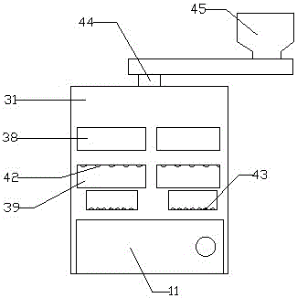
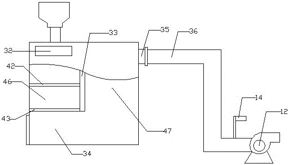
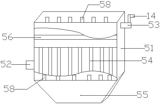

Image

  • Method and device for dry treatment of waste incineration flue gas
  • Method and device for dry treatment of waste incineration flue gas
  • Method and device for dry treatment of waste incineration flue gas

Examples


Embodiment Construction

[0048] The technical solutions of the present invention will be described in detail below through specific examples.

[0049] A dry treatment method for waste incineration flue gas, the steps are as follows: put the waste to be treated into the preheated incinerator for primary combustion, and at the same time add calcium oxide through the top, and then the flue gas goes down through the grate and enters the secondary combustion chamber After secondary combustion, the burned flue gas enters the main heat exchanger from the flue gas outlet for heat exchange and cooling; after the flue gas passes through the main heat exchanger for heat exchange and cooling, it enters the flue gas constant temperature adjustment device; through the constant temperature adjustment of the flue gas , keep the flue gas temperature at 150-250°C, and then carry out bag dust removal on the flue gas through the purification integrated device, fixed bed activated carbon adsorption and purification up to t...


PUM

PropertyMeasurementUnit
particle sizeaaaaaaaaaa

Abstract

The invention belongs to the technical field of garbage incineration treatment, and particularly relates to a garbage incineration smoke gas dry process treatment method and a garbage incineration smoke gas dry process treatment device. Garbage to be treated is put into a preheated incineration furnace to be subjected to primary combustion, meanwhile, calcium oxide is added through the top, next, smoke gas descends to enter a secondary combustion chamber through a fire grate to be subjected to secondary combustion, and then, the combusted smoke gas is subjected to heat exchange to 150 to 250 DEG C from a smoke gas outlet (the temperature is properly higher than the dew point corrosion temperature and lower than the acceptable maximum temperature of subsequent smoke gas treatment equipment such as dust removal equipment and fans); then, the smoke gas is subjected to cloth bag dust removal and fixed bed activated carbon adsorption purification, after standards are reached, the smoke gas is led to a chimney through a draught fan to be exhausted, and in addition, material supply and air supply are controlled, so that the oxygen content in the exhausted smoke gas is in a reasonable interval being 5 to 13 percent.

Description

technical field [0001] The invention belongs to the technical field of garbage treatment, in particular to a method and device for dry treatment of garbage incineration flue gas. Background technique [0002] The disposal of garbage and some hazardous wastes is currently mostly carried out by combustion process. In order to prevent the production of dangerous, toxic and harmful substances such as dioxin, secondary combustion is often used for combustion, and the temperature of waste is required to be above 850°C during secondary combustion. In order to improve the quality of flue gas emission, when the incinerator is used, the secondary combustion chamber must be preheated to a certain temperature (about 400°C) with the help of auxiliary fuel or heat source before it can receive waste combustion flue gas from the primary combustion chamber. Therefore, if the combustion process is used to treat garbage, domestic garbage and hazardous waste, the secondary combustion chamber m...

Claims


Application Information

Patent Timeline
Patent Type & Authority Patents(China)
IPC IPC(8): F23G5/16F23G5/44F23G5/46F23J15/00F23L15/00B01D46/02B01D53/02C02F9/10
CPCY02E20/34
Inventor 王惠生
Owner 王惠生
Learn More