Novel stripping element tight connecting device

A connecting device and stripping technology, used in the petroleum industry, cracking, catalytic cracking, etc.

Active Publication Date: 2014-12-17
LUOYANG ZHIDA PETROCHEM ENG
View PDF4 Cites 0 Cited by
  • Summary
  • Abstract
  • Description
  • Claims
  • Application Information

AI Technical Summary

Problems solved by technology

[0004] The purpose of the present invention is to solve the deficiencies in the prior art, and provide a novel stripping element sealing connection device, the technical problem to be solved is to ensure the free expansion and d

Method used


Image

  • Novel stripping element tight connecting device
  • Novel stripping element tight connecting device
  • Novel stripping element tight connecting device

Examples


Embodiment Construction

[0033] In order to further explain the technical means and effects that the present invention takes to achieve the intended purpose of the invention, below in conjunction with the accompanying drawings and preferred embodiments, the specific implementation and structure of a new type of stripping element sealing connection device proposed according to the present invention , features and their effects are described in detail below.

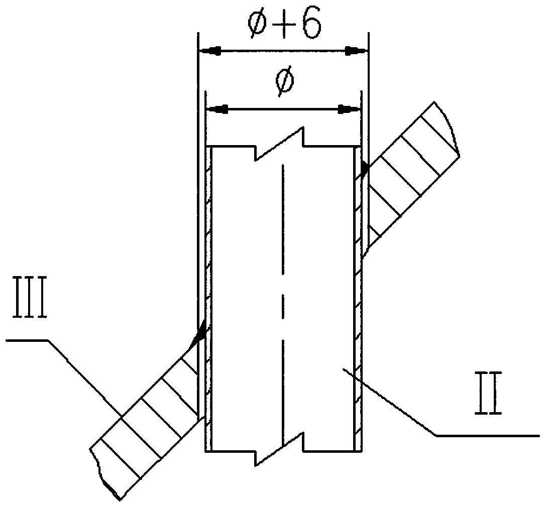
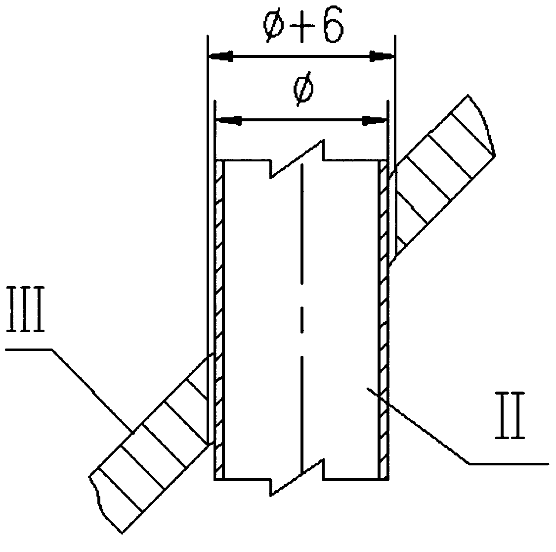
[0034] figure 2 It is a structural schematic diagram of the novel stripping element sealing connection device of the present invention. Such as figure 2 As shown, the present invention proposes a novel stripping element sealing connection device that is easy to expand and seal the stripping element. The stripping steam riser II passes through the conical baffle III, and the novel stripping element sealing connection device I seals and connects the stripping steam riser II and the conical baffle III. This novel stripping element sealing connec...


PUM


Abstract

The invention relates to a novel stripping element tight connecting device. A stripping steam vertical pipe passes through a cone-shaped baffle plate, and the stripping element tight connecting device is tightly connected with the stripping steam vertical pipe and the cone-shaped baffle plate. The stripping element tight connecting device comprises a compressing baffle plate, a connecting plate, a compressing ring, a silk screen, a sleeve and ceramic fibers, wherein the inner side face of the compressing baffle plate is fixedly connected with the stripping steam vertical pipe, the upper end of the connecting plate is fixedly connected with the compressing baffle plate, the lower end of the connecting plate is fixedly connected with the compressing ring, the compressing ring extends into the sleeve, the silk screen is located below the compressing ring and meanwhile is arranged on the top of a circular gap between the sleeve and the stripping steam vertical pipe, the ceramic fibers are filled in the circular gap below the silk screen, the sleeve is fixedly connected with the cone-shaped baffle plate, and the circular gap is formed between the lower end opening of the sleeve and the stripping steam vertical pipe. According to the technical scheme, not only can the free swelling deformation between the cone-shaped baffle plate and the stripping steam vertical pipe be ensured, but also the device has the sealing effect and can be used for effectively preventing the stripping steam vertical pipe from being worn through.

Description

technical field [0001] The invention relates to a stripping section of a coaxial settling-regenerator in a catalytic cracking unit of a refinery, comprising a conical baffle, an annular baffle, and a stripping steam standpipe. Background technique [0002] The function of the stripping section of the catalytic cracking coaxial settler is to desorb the oil and gas adsorbed by the unborn catalyst flowing downward in the settler by the high-temperature steam flowing upward in the stripping section, which can not only increase the yield of oil and gas, but also Reduces the scorching load due to hydrocarbons being carried into the regenerator. There are two commonly used structural forms in the stripping section, namely the ring-disk type and the herringbone baffle type. The typical structure of the current industrial application is a ring-disk type, usually multi-layer, and each layer is a single ring or a single disc staggered arrangement. The function of the stripping steam ...

Claims


Application Information

Patent Timeline
IPC IPC(8): C10G11/00
Inventor 雷龙超杨龙须
Owner LUOYANG ZHIDA PETROCHEM ENG
Why Eureka
Try Eureka