extracorporeal blood treatment device
An extracorporeal blood treatment and blood technology, applied in blood filtration, other medical devices, suction devices, etc.
- Summary
- Abstract
- Description
- Claims
- Application Information
AI Technical Summary
Problems solved by technology
Method used
Image

Examples
example 1
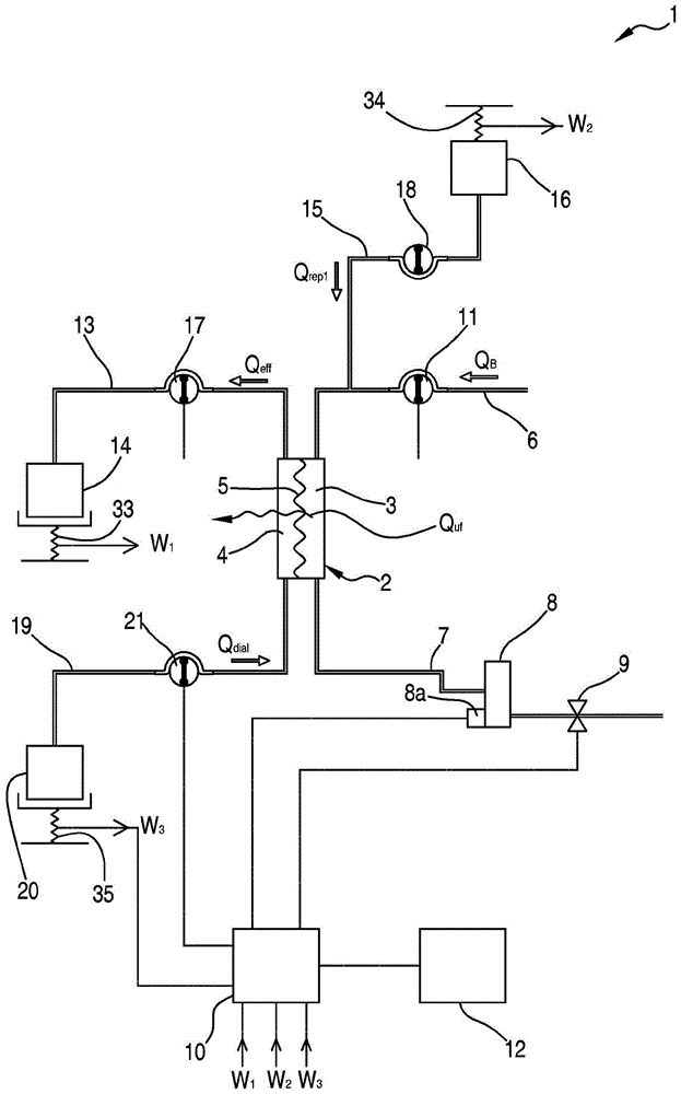
[0212] Figure 5 A first example of implementation of the control process already described herein above is shown.
[0213] In this embodiment, the control process includes:
[0214] - Determined at detection point T i previous time period T retro The value V of fluid removed from the patient pfr_removed ;
[0215] - Determined at detection point T i After the time period T prosp The value V of the fluid that will be removed from the patient pfr_need , so as to realize the detection point T i previous time period T retro and detection point (T i ) after the time period T prosp The total time period fluid withdrawal rate Q pfr The set value Q of pfr_set ;exist Figure 5 Medium, T retro equal to T prosp : of course this can be the preferred choice, it should be noted that T retro Can also be used with T prosp different.
[0216] - Setpoint Q based on fluid withdrawal rate pfr_set , at the detection point (T i ) after the time period T prosp The value of the ...
example 2
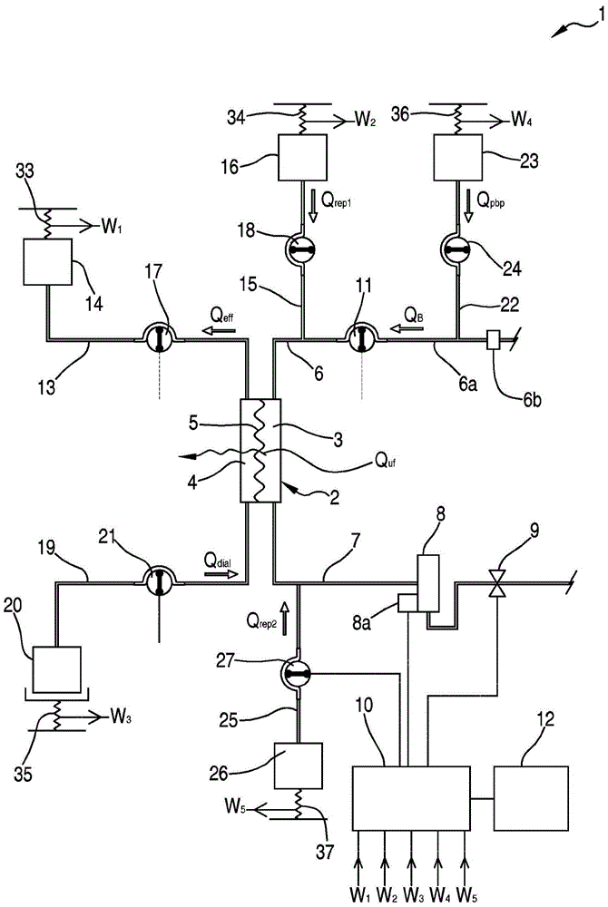
[0239] Image 6 A second example of the implementation of the control process already described herein above is shown.
[0240] In this case, the procedure aims to achieve the most accurate patient fluid withdrawal over a predefined period of time. In this example, multiple time periods of constant duration ΔT are preset, starting at preset time T00:
[0241] T 00 ;T 00 +ΔT;…;T 00 +k·ΔT
[0242] and ends at the preset end time
[0243] T 00 +ΔT;T 00 +2ΔT;…;T 00 +(k+1)·ΔT.
[0244] In this variant, the purpose of the control unit 10 is to deliver precise patient fluid withdrawal instructions within a predefined time window, eg to match staff shifts or simply "on the hour" (13:00, 14:00, 15:00, ...).
[0245] When calculating the instantaneous Q pfr_new , the "detection point T" can be completed as follows i ":
[0246] - at each processing interruption (downtime);
[0247] - every time the flow setting is changed;
[0248] - at each predefined time window limit ...
example 3
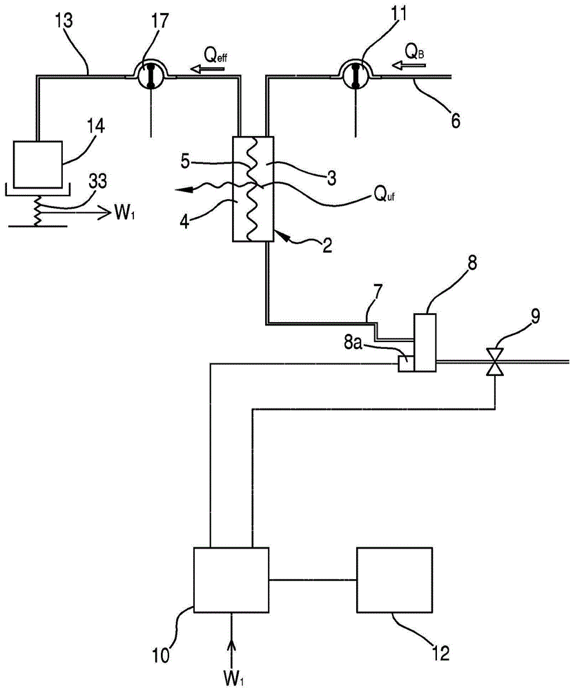
[0283] The following example and example 2 (reference image 3 and Image 6 ) similarly, showing the effective part T eff is calculated and used, in this case by placing the detection point T i The duration of the subsequent time period is reduced by a first amount associated with the average bag change time expected to take in the following time period and a second amount associated with downtime due to an alarm condition to determine the effective portion T eff .
[0284] Apply algorithm (6) to image 3 device, assuming:
[0285] - Operator initial setting Q pfr_set =100ml / h;
[0286] - Predefined time windows: 0:00; 4:00; 8:00; 12:00; 16:00; 20:00;
[0287] - Detection time T i : 10:30;
[0288] - The actual fluid withdrawn within [4:00; 8:00] measured by scale 33 is V pfr(k-1) =396ml;
[0289] - The fluid actually withdrawn in [4:00; 10:30] measured by the scale 33 is V pfr(0) =245ml;
[0290] - The number of bag changes planned in [10:30; 12:00] is: N change...
PUM
 Abstract
Description
Claims
Application Information
 - Generate Ideas
- Intellectual Property
- Life Sciences
- Materials
- Tech Scout
- Unparalleled Data Quality
- Higher Quality Content
- 60% Fewer Hallucinations
Browse by: Latest US Patents, China's latest patents, Technical Efficacy Thesaurus, Application Domain, Technology Topic, Popular Technical Reports.
© 2025 PatSnap. All rights reserved.Legal|Privacy policy|Modern Slavery Act Transparency Statement|Sitemap|About US| Contact US: help@patsnap.com