
Method and device for controlling mode light power

An optical power control and mode technology, applied in electromagnetic wave transmission systems, electrical components, transmission systems, etc., can solve the problems that affect the transmission performance of the system, the large bending loss of high-order modes, and the sensitivity to loss differences, and achieve the effect of improving transmission performance.

Inactive Publication Date: 2014-12-10
BEIJING UNIV OF POSTS & TELECOMM
View PDF10 Cites 15 Cited by
  • Summary
  • Abstract
  • Description
  • Claims
  • Application Information

AI Technical Summary

Problems solved by technology

However, in the actual transmission link based on few-mode fiber, compared with multiple channels of single-mode fiber, the multi-mode of few-mode fiber is more sensitive to the loss difference in the transmission process
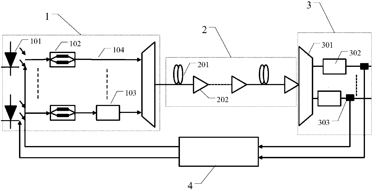
[0003] Due to the different attenuation performance of different modes, the different amplification gains of Erbium-doped Optical Fiber Amplifier (EDFA) for different modes, the uneven attenuation of different modes at optical switching nodes, and the higher-order modes have greater bending Due to factors such as loss, mode-related dispersion, and inter-mode coupling, the power of each mode (especially the high-order mode) is not consistent after the multiplexing mode of the same mode power is transmitted through a single-span few-mode fiber at the transmitter, or after multi-span few-mode fiber transmission and EDFA amplification. , in the case of mode coupling, seriously affects the overall transmission performance of the system

Method used


Image

  • Method and device for controlling mode light power
  • Method and device for controlling mode light power
  • Method and device for controlling mode light power

Examples


Embodiment

[0070] The derivation process of the input power ratio is described below by taking four modes and using the optical signal-to-noise ratio to determine the input power ratio as an example, but does not limit the protection scope of the present invention. The derivation process of the input power ratio is as follows:

[0071] Taking multi-span and few-mode transmission and EDFA amplification as an example, the evaluation of mode division multiplexing transmission performance is carried out. Assuming that the few-mode fibers used in the few-mode transmission system are of the same type, only the mode-dependent loss α is considered i and EDFA for different modes of differential amplification gain It can be obtained by the following calculation that at the receiving end, the received power of each mode can be expressed as

[0072] P out i = P in i Π ...


PUM


Abstract

The invention discloses a method and a device for controlling a mode light power, and relates to the technical field of mode division multiplexing transmission. The device comprises a sending end, a transmission link, a receiving end and a feedback control unit, wherein the sending end, the transmission link and the receiving end are sequentially connected; the feedback control unit is connected with the sending end and the receiving end respectively; the transmission link further comprises a few-mode optical fibre and an optical fibre amplifier. According to the method and the device disclosed by the invention, the receiving power or the light signal-to-noise ratio of the light beam of each mode are acquired through the receiving end, an input power ratio is determined by the feedback control unit according to the receiving power or the light signal-to-noise ratio, the input power of the light beam is adjusted by the sending end according to the input power ratio, thus realizing control on the input power of each mode, and improving the overall transmission performance of the system.

Description

technical field [0001] The invention relates to the technical field of mode division multiplexing transmission, in particular to a mode optical power control method and device. Background technique [0002] At present, the mode-division multiplexing transmission technology based on few-mode fiber has received extensive attention and research as an important solution to further improve transmission capacity. The key to the mode-division multiplexing transmission system in this technology is to use different modes as channels to transmit signals of different channels, so that the transmission capacity will be doubled by the number of modes in the optical fiber. Few-mode fiber not only inherits the multi-mode characteristics of multi-mode fiber, but also can carry out long-distance transmission just like single-mode fiber. However, in the actual transmission link based on few-mode fiber, compared with multiple channels of single-mode fiber, the multi-mode of few-mode fiber is ...

Claims


Application Information

Patent Timeline
Patent Type & Authority Applications(China)
IPC IPC(8): H04B10/564
Inventor 高冠军赵永利张杰刘俊彦张楷杨辉
Owner BEIJING UNIV OF POSTS & TELECOMM
Learn More