
Torsional vibration signal detection method and device for engine crankshaft

A signal detection and engine technology, which is used in measuring devices, measuring ultrasonic/sonic/infrasonic waves, instruments, etc., can solve the problems of inability to obtain stable and effective torsional vibration signals, poor adaptability, and unsuitable for engine crankshaft torsional vibration signal acquisition.

Active Publication Date: 2014-12-10
DONGFENG CUMMINS ENGINE
View PDF1 Cites 17 Cited by
  • Summary
  • Abstract
  • Description
  • Claims
  • Application Information

AI Technical Summary

Problems solved by technology

[0002] At present, the laser Doppler torsional vibration meter and magnetoelectric sensor are mostly used in engine torsional vibration measurement. The laser Doppler torsional vibration meter is sensitive to the vibration of the engine bench, and the equipment is huge, so it can only be used on the engine bench. It is suitable for portable work, and the cost is high. If the table vibrates greatly, it will not be possible to obtain a stable signal
Magnetoelectric sensor testing needs to process signal acquisition disks for different models, which has poor adaptability, and has high requirements for testing distance and installation location. If the testing distance is too large or too small, and there is vibration in the installation location, it is impossible to obtain stable and effective results. torsional vibration signal
[0003] The above test method is not suitable for the collection of engine crankshaft torsional vibration signals due to the above defects

Method used


Image

  • Torsional vibration signal detection method and device for engine crankshaft
  • Torsional vibration signal detection method and device for engine crankshaft
  • Torsional vibration signal detection method and device for engine crankshaft

Examples


Embodiment Construction

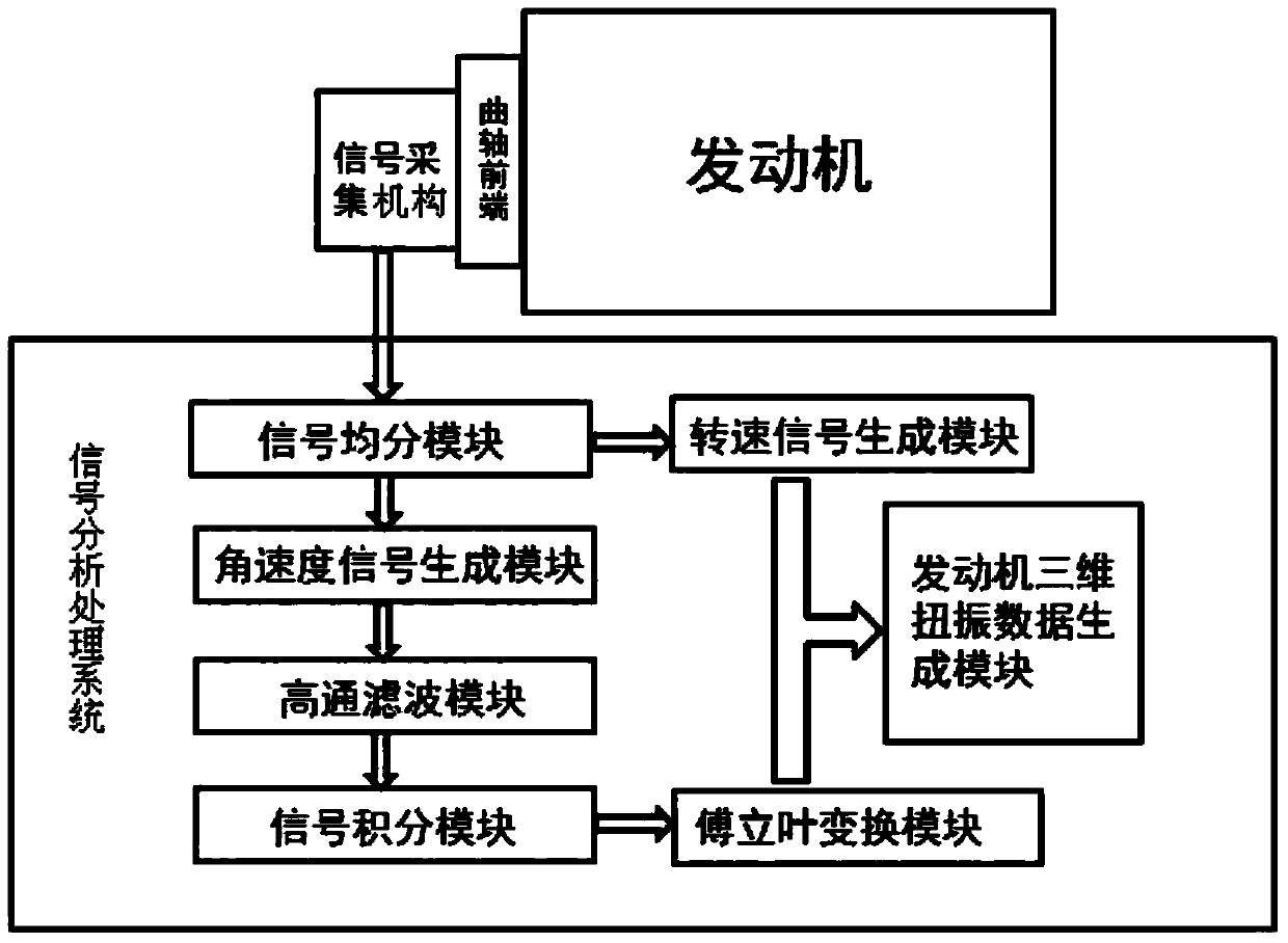
[0046] The examples of the present invention will be further described below in conjunction with the accompanying drawings. A kind of engine crankshaft torsional vibration signal detection method of the present invention is characterized in comprising the following steps:

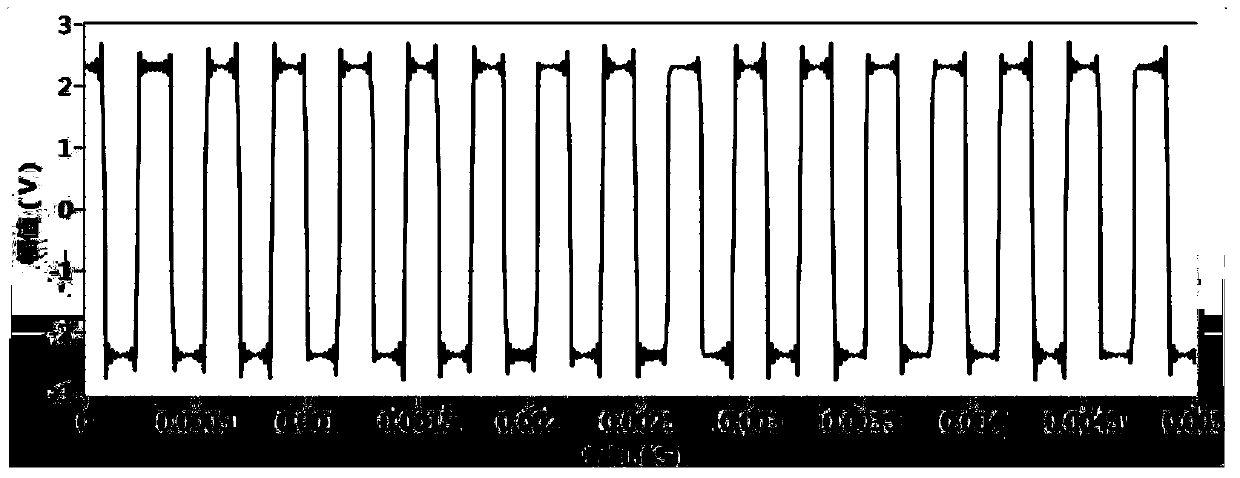
[0047] 1) Use the encoder of the signal acquisition mechanism to collect the rotation pulse signal Q of the front end of the engine crankshaft whose time is T, where T is an integer multiple of R, and divide the signal into pulse signals with each period of time R Q k , k = 1,2 , · · · , T R ; Such as figure 2 ;

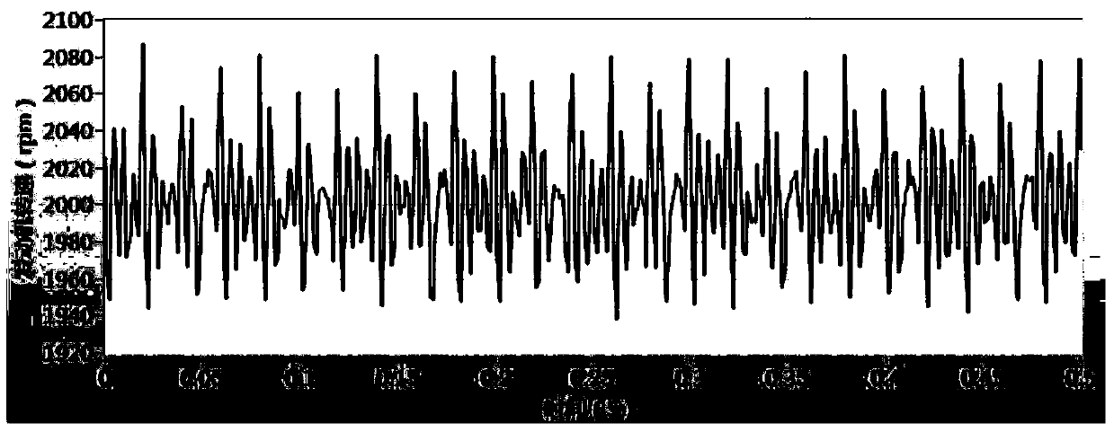
[0048] 2) Divide the pulse signal Q equally k Converted to a speed signal n k and the angular velocity signal ω k According to the following formula: n k = ...


PUM


Abstract

The invention discloses a torsional vibration signal detection method and device for an engine crankshaft. The torsional vibration signal detection method includes that gathering rotation pulse signals of the front end of the engine crankshaft, converting the rotation pulse signals into rotating speed signals and angular speed signals, extracting the high-frequency component from the angular speed signals, performing point-by-point integration, converting a high-frequency time domain signal obtained through integration into a frequency domain signal through fast Fourier point-by-point transformation, and inputting the rotating speed signal nk of each equalization signal Qk and angular displacement frequency domain signals Yk into a three-dimensional coordinate system in sequence through a three-dimensional torsional vibration data generating module of the engine so as to obtain three-dimensional torsional vibration data of the engine, wherein the horizontal coordinate is related to the torsional vibration frequency of the engine, the left vertical coordinate is related to the amplitude, and the right vertical coordinate is related to the rotating speed. The torsional vibration signal detection device uses the combined design, the mounting is facilitated, and the detection is not influenced by the engine and outside vibration; the torsional vibration signal detection device is good in reliability, high in measuring precision, convenient to analyze and calculate, strong in adaptability, light in weight and strong in portability.

Description

technical field [0001] The invention belongs to the field of engine testing, and in particular relates to a detection method and device for an engine crankshaft torsional vibration signal. Background technique [0002] At present, laser Doppler torsional vibration instruments and magnetoelectric sensors are mostly used for engine torsional vibration measurement. Laser Doppler torsional vibration instruments are sensitive to the vibration of the engine bench, and the equipment is huge, so it can only be used on the engine bench. It is suitable for portable work, and the cost is relatively high. If the table vibrates heavily, it will not be possible to obtain a stable signal. Magnetoelectric sensor testing needs to process signal acquisition disks for different models, which has poor adaptability, and has high requirements for testing distance and installation location. The testing distance is too large or too small, and there is vibration in the installation location, so it i...

Claims


Application Information

Patent Timeline
Patent Type & Authority Applications(China)
IPC IPC(8): G01H17/00
Inventor 宋单平王勇
Owner DONGFENG CUMMINS ENGINE
Learn More