An oil injection exhaust device and a bearing chamber

A technology of exhaust device and bearing chamber, which is applied in the direction of bearing components, shafts and bearings, rigid supports of bearing components, etc., and can solve problems such as unreasonable design of oil injection and exhaust devices, oil leakage, and oil accumulation that cannot be effectively recovered.

Active Publication Date: 2017-12-12
CHINA SHENHUA ENERGY CO LTD +2
View PDF10 Cites 0 Cited by
  • Summary
  • Abstract
  • Description
  • Claims
  • Application Information

AI Technical Summary

Problems solved by technology

[0002] Traditionally, the design of the oil injection and exhaust device on the bearing chamber of the motor of the high-pressure fluidized fan is unreasonable, causing the oil and gas in the bearing chamber to be discharged through the oil injection and exhaust device. Oil leakage often occurs in the hole, especially for high-speed equipment that uses thin oil seal lubrication, the oil leakage phenomenon is more serious, and oil accumulation leaks to the outside of the motor, affecting the site environment and civilized production

Method used


Image

  • An oil injection exhaust device and a bearing chamber
  • An oil injection exhaust device and a bearing chamber
  • An oil injection exhaust device and a bearing chamber

Examples


Embodiment Construction

[0023] Specific embodiments of the present invention will be described in detail below in conjunction with the accompanying drawings. It should be understood that the specific embodiments described here are only used to illustrate and explain the present invention, and are not intended to limit the present invention.

[0024] In the present invention, unless stated to the contrary, the used orientation words such as "up and down" usually refer to the up and down of the oil injection and exhaust device in the vertical direction when in use.

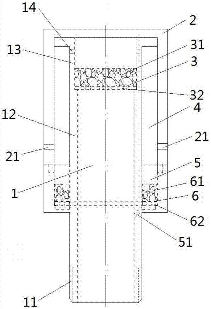
[0025] see figure 1 , The oil injection and exhaust device provided by the present invention includes: an oil injection and exhaust pipe 1;

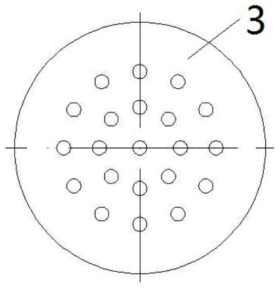
[0026] The volatilized oil gas in the bearing chamber or other equipment enters the above-mentioned oil injection and exhaust device and is separated by the oil and gas separation filter 3, which can effectively reduce the oil content of the oil gas. The separated oil flows downward through the oil ...


PUM


Abstract

The invention discloses an oil injection exhaust device and a bearing chamber. The oil injection exhaust device comprises: an oil injection exhaust pipe (1); and an oil and gas separation filter screen (3), the oil and gas separation filter screen (3) is detachable installed in the oil injection exhaust pipe (1). The above-mentioned oil injection and exhaust device has a simple structure and low manufacturing cost. After the oil and gas are separated by the oil and gas separation filter (3), the oil content of the oil and gas can be effectively reduced, and the separated oil flows downward through the oil injection exhaust pipe (1), and the gas is discharged upward. , so that the oil in the oil and gas can be effectively recovered, and the oil leakage phenomenon of the oil injection and exhaust device can be improved. When the oil is injected, the oil and gas separation filter (3) can be removed.

Description

technical field [0001] The invention relates to the field of engineering machinery, in particular to an oil injection and exhaust device and a bearing chamber. Background technique [0002] Traditionally, the design of the oil injection and exhaust device on the bearing chamber of the motor of the high-pressure fluidized fan is unreasonable, causing the oil and gas in the bearing chamber to be discharged through the oil injection and exhaust device. Oil leakage often occurs in the hole, especially for high-speed equipment that uses thin oil seal lubrication, the oil leakage phenomenon is more serious, and the accumulated oil leaks to the outside of the motor, affecting the site environment and civilized production. [0003] Therefore, it is desirable to have an oil injection and exhaust device capable of avoiding or at least reducing the oil leakage of the oil injection and exhaust device. Contents of the invention [0004] The object of the present invention is to provid...

Claims


Application Information

Patent Timeline
Patent Type & Authority Patents(China)
IPC IPC(8): F16C35/00
Inventor 宋治峰
Owner CHINA SHENHUA ENERGY CO LTD
Why Eureka
Try Eureka