
Yarn gripper for air-jet loom

A technology of air-jet looms and yarn grippers, which is applied in looms, textiles, textiles, and papermaking, etc. It can solve the problems of edge weave jumping, loose edge tissue, and edge quality deterioration, and achieves convenient installation and maintenance. The effect of preventing selvedge jumping and simple structure

Active Publication Date: 2016-02-24
QINGDAO TIANYI GROUP RED FLAG TEXTILE MACHINERY
View PDF7 Cites 0 Cited by
  • Summary
  • Abstract
  • Description
  • Claims
  • Application Information

AI Technical Summary

Problems solved by technology

[0004] When weaving fabrics with low warp and weft density or low warp and weft twist weaving friction, the tension of the upper and lower warp yarns will cause the edge weft yarn to shrink in the weft direction, and the edge tissue will be looser, which will affect the quality of the finished fabric. The bracing will cause the weaving edge to jump, which will cause the quality of the edge to deteriorate further. The existing yarn gripper has a complex structure, and it is inconvenient to adjust the gripping pressure and length, which cannot meet the needs of actual operation.

Method used


Image

  • Yarn gripper for air-jet loom
  • Yarn gripper for air-jet loom
  • Yarn gripper for air-jet loom

Examples


Embodiment Construction

[0028] The present invention will be further described in detail below in conjunction with the accompanying drawings and specific embodiments, but the present invention is not limited to these embodiments.

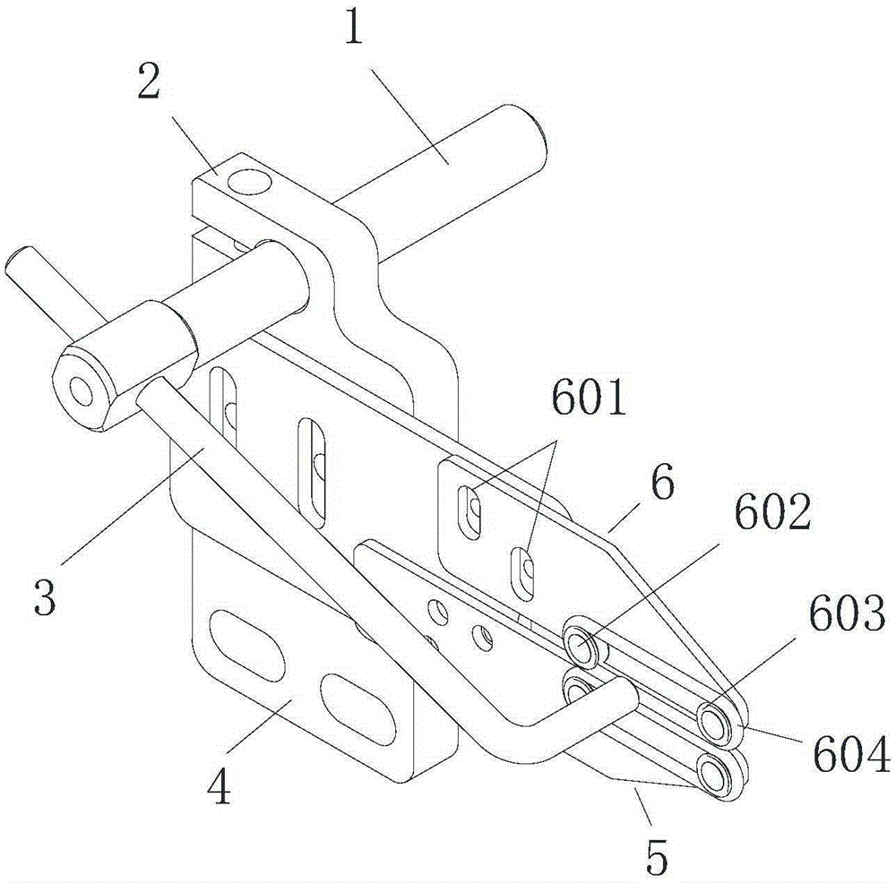
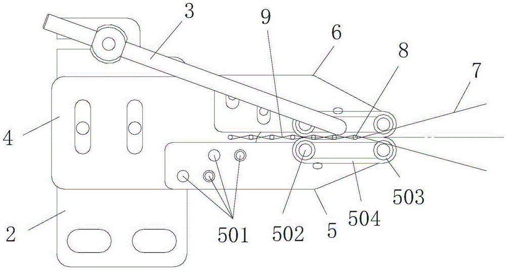
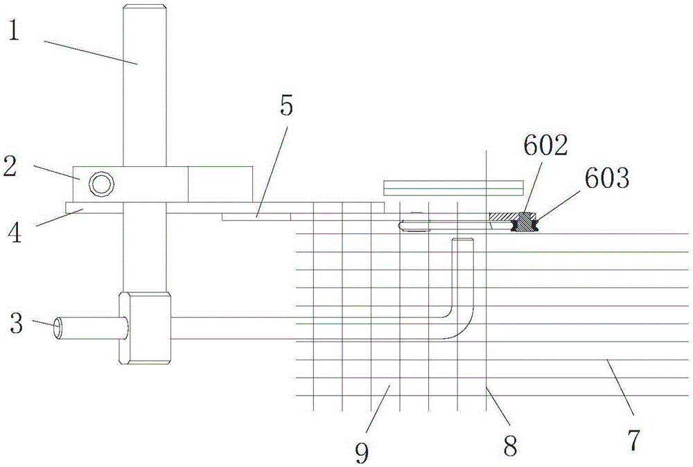
[0029] Such as Figure 1 to Figure 3 As shown, a yarn gripper for an air-jet loom includes an upper pressing plate 6 and a lower supporting plate 5, the upper pressing plate 6 and the lower supporting plate 5 are both arranged on the connecting plate 4; the upper pressing plate 6 is provided with two upper roller shafts 602 Each upper roller shaft 602 is respectively sleeved with an upper roller 603, and the circumference of each upper roller 603 is respectively provided with a first groove. The two upper rollers 603 are connected by an upper rubber belt 604, and the upper rubber belt 604 is inserted into the first In a groove; the lower supporting plate 5 is provided with two lower roller shafts 502, each lower roller shaft 502 is respectively sleeved with a lower roller ...


PUM


Abstract

The invention discloses a yarn clamping device for an air-jet room. The yarn clamping device comprises an upper pressing plate and a lower supporting plate. Both the upper pressing plate and the lower supporting plate are arranged on a connection plate. Two upper rolling wheel shafts are arranged on the upper pressing plate. Upper rolling wheels are arranged on all the upper rolling wheel shafts respectively in a sleeved mode. First grooves are formed in the circumferences of all the upper rolling wheels respectively. The two upper rolling wheels are connected through upper rubber belts. The upper rubber belts are arranged in the first grooves. Two lower rolling wheel shafts are arranged on the lower supporting plate. Lower rolling wheels are arranged on all the lower rolling wheel shafts respectively in a sleeved mode. Second grooves are formed in the circumferences of all the lower rolling wheels respectively, the two lower rolling wheels are connected through lower rubber belts, and the lower rubber belts are arranged in the second groove. Weft yarn clamping gaps are formed through match of the upper rubber belts and the lower rubber belts, and both the contact pressure and the contact length of the upper rubber belts and the lower rubber belts can be adjusted. By means of the yarn clamping device, effective weft yarn clamping can be achieved, and quality of finished fabric is guaranteed.

Description

technical field [0001] The invention relates to an air-jet loom, in particular to a yarn gripper for an air-jet loom. Background technique [0002] Air-jet weft insertion refers to the method of leading the weft yarn through the shed by the traction force generated by the jetted airflow on the weft yarn. It is characterized by high speed, high tension and small shed, and has high requirements for raw yarn and semi-finished products. As a passive weft insertion method, air-jet weft insertion has low tension and no control when the weft yarn flies over the shed. Therefore, it lacks sufficient traction for weft yarns with high linear density or fancy yarns. The quality of weft insertion is greatly affected, and fabric defects such as weft shrinkage and weft return are prone to occur. [0003] The weft insertion process of the existing air-jet loom is roughly as follows: after the weft yarn is released from the bobbin, it passes through the tension device, and the weft yarn of ...

Claims


Application Information

Patent Timeline
Patent Type & Authority Patents(China)
IPC IPC(8): D03D47/34
Inventor 高玉刚刘培德逄浩然范龙霄霍艳慧周昱霖
Owner QINGDAO TIANYI GROUP RED FLAG TEXTILE MACHINERY
Learn More