Novel polishing machine

A technology of polishing machine and polishing mechanism, which is applied in the direction of surface polishing machine tools, grinding/polishing equipment, metal processing equipment, etc., and can solve the problem of uneven polishing effect of sheet metal workpieces, reduced polishing work efficiency, small hinge size, etc. question

Inactive Publication Date: 2014-12-10
SUZHOU AOLIN HARDWARE
View PDF7 Cites 10 Cited by
  • Summary
  • Abstract
  • Description
  • Claims
  • Application Information

AI Technical Summary

Problems solved by technology

[0002] Sheet-shaped metal workpieces such as hinges will have burrs or scratches on the surface after processing and forming, which will affect the use. Therefore, a polishing machine is required to polish the surface of such sheet-shaped metal workpieces; the polishing machine includes conveying metal workpieces. The conveying mechanism and the polishing mechanism for polishing metal workpieces. The polishing mechanism includes a polishing piece and a polishing drive mechanism that drives the movement of the polishing piece. The conveying mechanism includes a conveyor belt and a conveying drive mechanism that drives the movement of the conveyor belt; After the mechanism transports the sheet metal workpiece in place, the polishing drive mechanism drives the polishing piece to complete the polishing action, and then continues to transport the sheet metal workpiece to the finished product end; since the traditional polishing machine is only equipped with one polishing piece, it is easy to have The sheet metal workpiece may not achieve the actual polishing effect, and the polishing effect of the sheet metal workpiece in different areas is not uniform, which requires rework, which reduces the polishing work efficiency; at the same time, the size of the hinge is usually small , the traditional polishing machine is difficult to effectively fix and polish the hinge metal sheet

Method used


Image

  • Novel polishing machine
  • Novel polishing machine

Examples


Embodiment Construction

[0017] The specific implementation manners of the present invention will be further described in detail below in conjunction with the accompanying drawings and embodiments. The following examples are used to illustrate the present invention, but are not intended to limit the scope of the present invention.

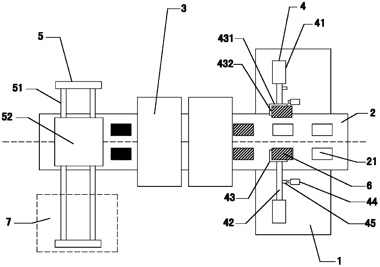
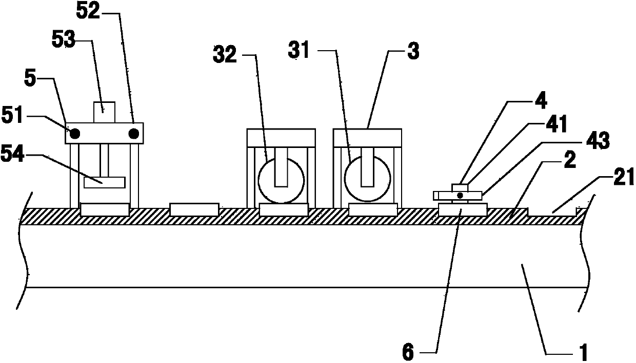
[0018] see figure 1 and figure 2 As shown, a new type of polishing machine includes a workbench 1, a conveyor belt 2, a polishing mechanism 3, a feeding mechanism 4 and a discharge mechanism 5. A relatively moving conveyor belt 2 is arranged above the workbench 1, and the conveyor belt 2 is made of non-magnetic metal. Conveyor belt, the top surface of conveyor belt 2 is provided with accommodating groove 21 for placing workpiece at intervals, and the depth of accommodating groove 21 is greater than 2 / 3 of the thickness of workpiece 6, and is less than the thickness of workpiece 6; Feeding mechanism 4 includes pushing oil cylinder 41, The push rod 42 that is arranged on ...


PUM


Abstract

The invention relates to a novel polishing machine which is suitable for polishing hinges, even in polishing effect and high in working efficiency. The novel polishing machine comprises a workbench, a conveying belt, a polishing mechanism, a feed mechanism and a discharge mechanism. The conveying belt moving relative to the workbench is arranged above the workbench and is a nonmagnetic metal conveying belt, containing grooves for containing workpieces are formed in the top face of the conveying belt at intervals, and the depth of the containing grooves is larger than 2 / 3 of the thickness of the workpieces and smaller than the thickness of the workpieces. The feed mechanism comprises a push oil cylinder, a push rod and a material push plate, wherein the push oil cylinder is used for pushing the material push plate to move towards the conveying belt. The polishing mechanism is arranged above the conveying belt. The discharge mechanism comprises a guide rail arranged above the workbench, a sliding block relatively sliding on the guide rail and a motor driving the sliding block to move. An air cylinder is arranged on the sliding block, an electromagnet is arranged at the output end of the air cylinder, and the air cylinder is used for pushing the electromagnet to move towards the top face of the conveying belt. A material receiving box is arranged at the bottom of the outer side of the guide rail.

Description

technical field [0001] The invention relates to a polishing device in the hinge processing production process, in particular to a novel polishing machine. Background technique [0002] Sheet-shaped metal workpieces such as hinges will have burrs or scratches on the surface after processing and forming, which will affect the use. Therefore, a polishing machine is required to polish the surface of such sheet-shaped metal workpieces; the polishing machine includes conveying metal workpieces. The conveying mechanism and the polishing mechanism for polishing metal workpieces. The polishing mechanism includes a polishing piece and a polishing drive mechanism that drives the movement of the polishing piece. The conveying mechanism includes a conveyor belt and a conveying drive mechanism that drives the movement of the conveyor belt; After the mechanism transports the sheet metal workpiece in place, the polishing drive mechanism drives the polishing piece to complete the polishing a...

Claims


Application Information

Patent Timeline
IPC IPC(8): B24B29/02
CPCB24B29/02
Inventor 贺卿
Owner SUZHOU AOLIN HARDWARE
Why Eureka
Try Eureka