Conveying and punching device special for lock cylinders

A technology of punching device and conveying device, applied in positioning device, clamping device, boring/drilling and other directions, can solve the problems of poor use stability and low work efficiency, and achieve high work efficiency, convenient operation and stable conveying. good effect

Active Publication Date: 2014-12-10
潘焱
View PDF5 Cites 3 Cited by
  • Summary
  • Abstract
  • Description
  • Claims
  • Application Information

AI Technical Summary

Problems solved by technology

In the machining process of the lock cylinder, it needs to be conveyed at first, and the operation of punching it is also needed according to the process requirements. In the prior art, conveyor belts are used to convey, and manual operations are used to punch holes one by one, which has poor stability in use. low work efficiency

Method used


Image

  • Conveying and punching device special for lock cylinders
  • Conveying and punching device special for lock cylinders
  • Conveying and punching device special for lock cylinders

Examples


Embodiment Construction

[0021] The specific implementation manner of the present invention will be described below in conjunction with the accompanying drawings.

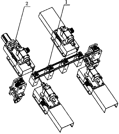
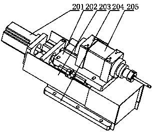
[0022] Such as figure 1 and figure 2 As shown, the special conveying and punching device for the lock cylinder of the present embodiment includes a conveying device 1, and a punching mechanism 2 is symmetrically installed on both sides of the conveying device 1. The structure of the punching mechanism 2 is: a base plate 204 is installed on the Frame 203, on the bottom plate 204 of frame 203, slide plate 202 is installed through a sliding mechanism, on slide plate 202, reducer 205 is fixed, and the output end of reducer 205 is equipped with a drill bit, and one end of frame 203 is also fixed with push cylinder 201, push cylinder 201 The output terminal of is connected with the slide plate 202.

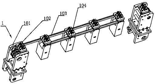
[0023] Such as image 3 and Figure 4 As shown, the structure of the conveying device 1 is as follows: a support base 101 is provided at inter...


PUM


Abstract

The invention relates to a conveying and punching device special for lock cylinders. The conveying and punching device comprises a conveying device, and the two sides of the conveying device are symmetrically provided with punching mechanisms. The structure of each punching mechanism is that a bottom plate is included, the bottom plate is provided with a mounting frame, a sliding plate is mounted through a sliding mechanism on the bottom plate placed on the frame, the sliding plate is fixedly provided with a fixed speed reducer, the output end of the speed reducer is provided with a drill bit, a push cylinder is further fixedly arranged at one end of the frame, and the output end of the push cylinder is connected with the sliding plate. The conveying and punching device special for the lock cylinders is compact and reasonable in structure and convenient to operate, the conveying device drives a clamping seat for conveying under the effect of a conveying chain, namely a fixed seat on the top of the clamping seat drives the lock cylinders to be conveyed forwards and stops when the lock cylinders are conveyed to the needed position. At the time, the operation process of punching is conducted on the lock cylinders, the conveying stability is good, and the working efficiency is high.

Description

technical field [0001] The invention relates to the technical field of punching mechanisms, in particular to a special conveying and punching device for lock cylinders. Background technique [0002] The lock cylinder is the main part that controls the opening of the lock. It is the heart of the lock. It refers to the core part that can be turned and driven by the key to move the lock. In the machining process of the lock cylinder, it needs to be conveyed at first, and the operation of punching it is also needed according to the process requirements. In the prior art, conveyor belts are used to convey, and manual operations are used to punch holes one by one, which has poor stability in use. Work efficiency is low. Contents of the invention [0003] Aiming at the above-mentioned shortcomings in the existing production technology, the applicant provides a special conveying and punching device for the lock cylinder with a reasonable structure, thereby improving the reliabili...

Claims


Application Information

Patent Timeline
Patent Type & Authority Applications(China)
IPC IPC(8): B23B41/00B23Q3/00B23Q7/00
CPCB23B41/00B23Q3/00B23Q7/03B23Q2703/10
Inventor 董仲伟
Owner 潘焱
Why Eureka
Try Eureka