Decoding method and device
A decoding method and decoding device technology, applied in the field of decoding method and device, capable of solving problems such as insufficient OTN service processing capacity, large resources, and consumption
- Summary
- Abstract
- Description
- Claims
- Application Information
AI Technical Summary
Problems solved by technology
Method used
Image
Examples
Embodiment 1
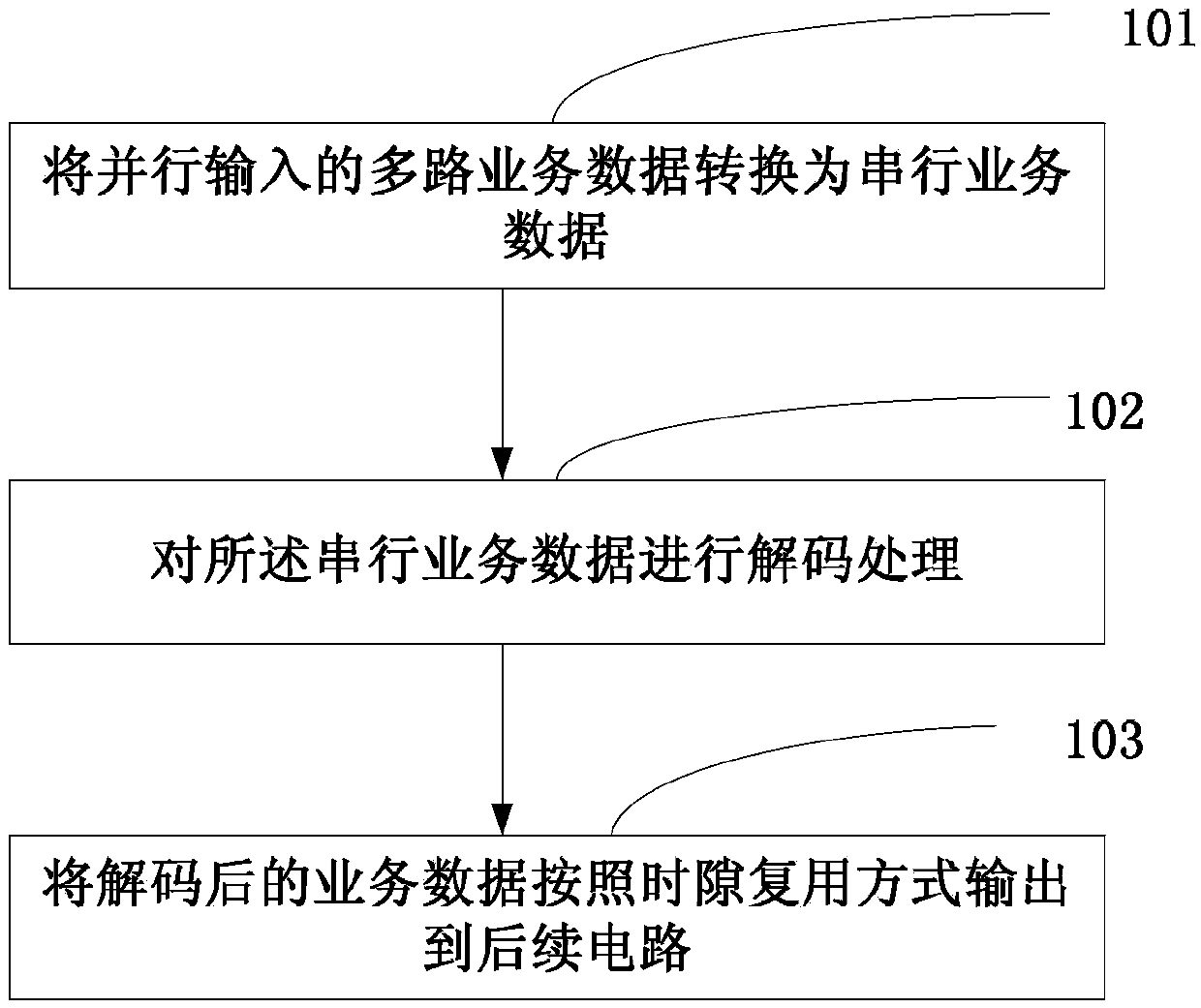
[0087] Such as figure 1 , this embodiment provides a decoding method, including the following steps:
[0088] Step 101: converting the multi-channel business data input in parallel into serial business data;
[0089] Step 102: Decoding the serial service data;
[0090] Step 103: output the decoded service data to subsequent circuits in a time slot multiplexing manner.
[0091] The decoding method of this embodiment can convert the multi-channel coded services input in parallel into serial services, and decode the serial services, and output the decoded data in a time slot multiplexing manner. The decoding method of this embodiment adopts The time-division multiplexing technology can make multi-channel business data share one decoding circuit, which meets the requirements of high-speed business processing, improves decoding efficiency and data throughput, avoids increasing decoding efficiency by adding decoding circuits, and reduces resource consumption. . The decoding meth...
Embodiment 2
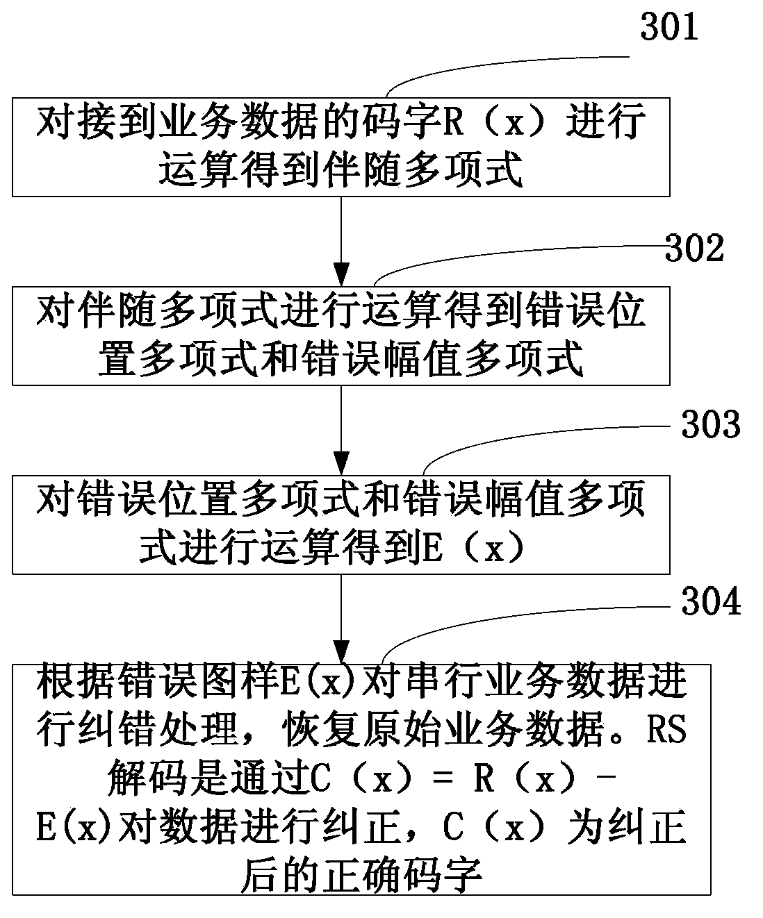
[0133] This embodiment introduces in detail the algorithm for parallel decoding of two bytes, and the bit width of the service data input in parallel is 256 bits:
[0134] Step 1: Parallel adjoint computation;
[0135] Let the codeword polynomial of the received business data be: R(x)=r n-1 x n-1 + r n-2 x n-2 +…+r 1 x+r 0 , the general adjoint polynomial coefficient s is calculated from the codeword polynomial of the business data j Calculation method, the calculation of the associated coefficient can be done by Figure 5 The arithmetic circuit shown completes:
[0136] s j = R ( α j ) = Σ i = 0 n - 1 r i · α ij ...
Embodiment 3
[0155] Such as Figure 11 As shown, this embodiment provides a decoding device, including: a conversion module, a decoding module and an output module;
[0156] The conversion module is used to receive multi-channel business data input in parallel, and convert the business data input in parallel into serial business data;
[0157] The decoding module is used to decode the serial service data;
[0158] The output module is used to output the decoded service data to subsequent circuits in a time slot multiplexing manner.
[0159] Such as Figure 12 As shown, the decoding device in this embodiment may further include: a bit width conversion module;
[0160] The bit width conversion module is used to process the bit width of the parallel input multi-channel business data before the conversion module converts the parallel-input multi-channel business data into serial service data, and convert the bit width of each channel of business data Convert to uniform bit width.
[0161]...
PUM
 Abstract
Description
Claims
Application Information
 - R&D
- Intellectual Property
- Life Sciences
- Materials
- Tech Scout
- Unparalleled Data Quality
- Higher Quality Content
- 60% Fewer Hallucinations
Browse by: Latest US Patents, China's latest patents, Technical Efficacy Thesaurus, Application Domain, Technology Topic, Popular Technical Reports.
© 2025 PatSnap. All rights reserved.Legal|Privacy policy|Modern Slavery Act Transparency Statement|Sitemap|About US| Contact US: help@patsnap.com


