A trench gate igbt chip
A trench gate and chip technology, applied in electrical components, circuits, semiconductor devices, etc., can solve the problems of increasing the difficulty and cost of the IGBT chip process, increasing the number of virtual gates, etc., and achieve the effect of increasing the trench density and improving the withstand voltage.
- Summary
- Abstract
- Description
- Claims
- Application Information
AI Technical Summary
Problems solved by technology
Method used
Image
Examples
Embodiment 1
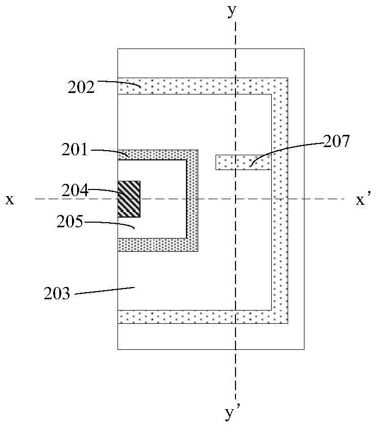
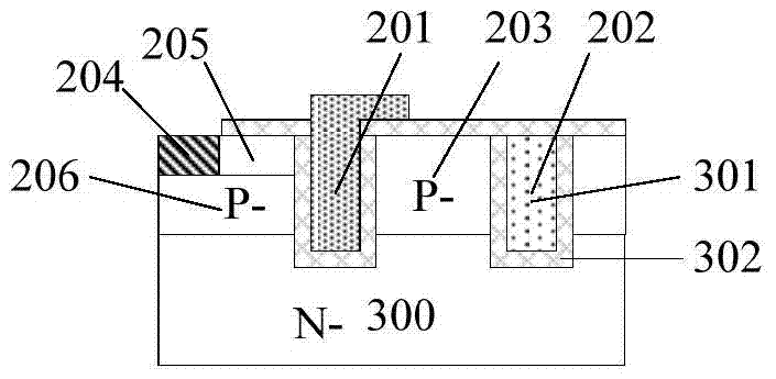
[0041] figure 2 It is a schematic plan view of the half-cell structure of the trench gate IGBT chip provided by Embodiment 1 of the present invention, and FIG. 3(a) is figure 2 The schematic cross-sectional view along the x-x' direction of the half-cell structure of the trench gate IGBT chip shown in Figure 3(b) is figure 2 The schematic cross-sectional view along the y-y' direction of the half-cell structure of the trench gate IGBT chip shown.
[0042] It should be noted that the trench gate IGBT chip described in Embodiment 1 is described by taking an N-type substrate material as an example.
[0043] Such as figure 2 As shown, the half-cell structure of the trench gate IGBT chip provided by Embodiment 1 of the present invention includes the first trench gate 201 and the second trench gate 202, between the first trench gate 201 and the second trench gate 202 isolated by the P-type region 203 . The half-cell structure further includes an emitter 204 and an N+ source regi...
Embodiment 2
[0059] The cellular structure of the trench gate IGBT chip described in Embodiment 2 has many similarities with the cellular structure of the trench gate IGBT chip described in Embodiment 1. For the sake of brevity, this embodiment only has the differences Make an emphatic explanation.
[0060] Figure 4 It is a schematic plan view of the half-cell structure of the trench gate IGBT chip provided by Embodiment 2 of the present invention, and FIG. 5(a) is Figure 4 The schematic cross-sectional view along the x-x' direction of the half-cell structure of the trench gate IGBT chip shown in Figure 5(b) is Figure 4 The schematic cross-sectional view along the y-y' direction of the half-cell structure of the trench gate IGBT chip shown.
[0061] Such as Figure 4 As shown, the half-cell structure of the trench gate IGBT chip described in the second embodiment includes three II trench gates 202 and four III trench gates 207, and the II trench gates 202 are respectively II -1 tren...
Embodiment 3
[0071] When the P-type sub-region is in a floating state, the turn-off speed will be reduced, and the turn-off loss will be increased, which will affect the performance of the safe working area of the chip. Therefore, it is necessary to lead out the P-type sub-region to the surface of the chip to realize an electrical ground connection. However, when the dummy gate trench gate forms a network structure, each P-type sub-region formed by division is isolated from each other. If each P-type sub-region is electrically connected to ground, according to the traditional method, it is necessary to connect each P-type sub-region to the ground. A lead-out window for leading the P-type sub-region to the chip surface is set on the suspended P-type sub-region, which will lead to a reduction in the number of grooves per unit area due to the existence of the lead-out window under the limitation of equipment and process level , that is, reducing the trench density, which is not conducive to...
PUM
 Abstract
Description
Claims
Application Information
 - R&D
- Intellectual Property
- Life Sciences
- Materials
- Tech Scout
- Unparalleled Data Quality
- Higher Quality Content
- 60% Fewer Hallucinations
Browse by: Latest US Patents, China's latest patents, Technical Efficacy Thesaurus, Application Domain, Technology Topic, Popular Technical Reports.
© 2025 PatSnap. All rights reserved.Legal|Privacy policy|Modern Slavery Act Transparency Statement|Sitemap|About US| Contact US: help@patsnap.com


