Annular combustion chamber bypass
A technology of annular combustion chamber and burner, applied in combustion chamber, continuous combustion chamber, combustion method, etc., can solve problems such as limitation of available partial load range of gas turbine, achieve simple assembly and disassembly, reduce emissions, combustion temperature high effect
- Summary
- Abstract
- Description
- Claims
- Application Information
AI Technical Summary
Problems solved by technology
Method used
Image
Examples
Embodiment Construction
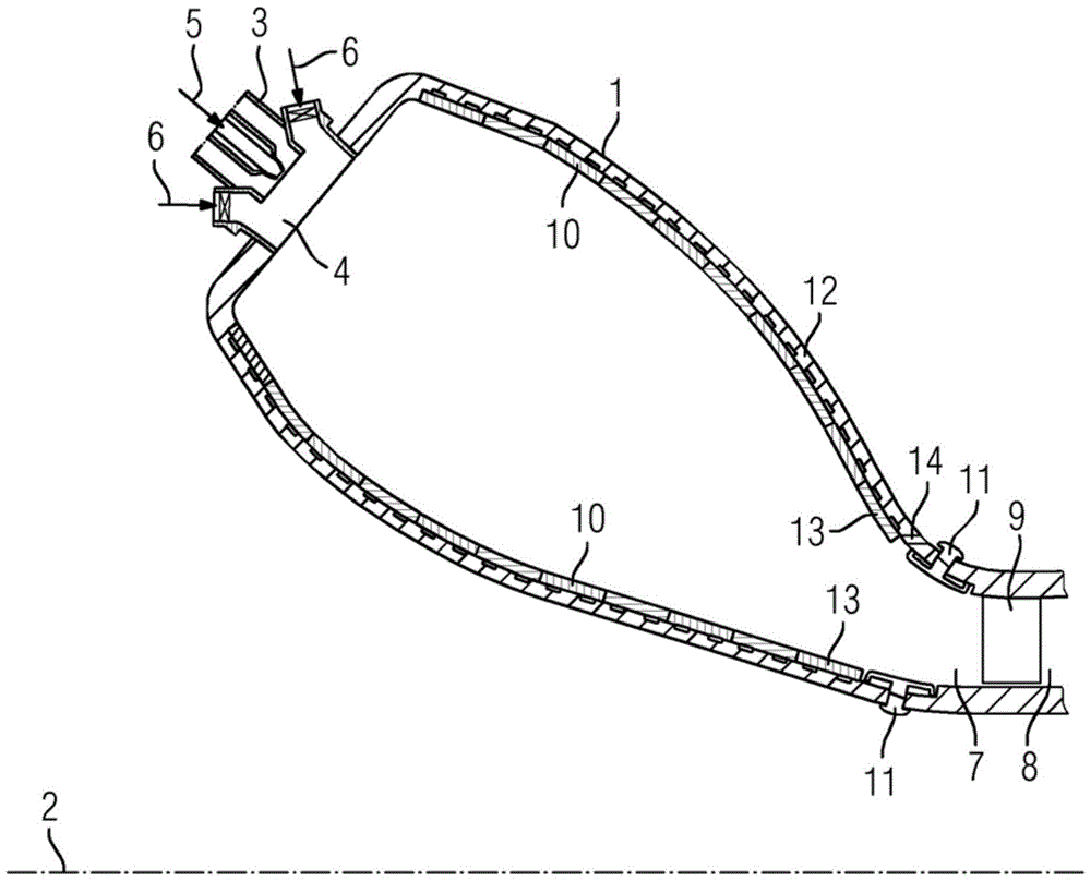
[0023] figure 1 The combustion system of the annular combustion chamber 1 according to the invention is shown schematically and by way of example. The annular combustion chamber 1 is formed by a closed ring arranged around the axis of rotation 2 . The burner 3 is arranged in the inlet 4 in the upper region of the combustion chamber 1 . There, fuel 5 is mixed with compressed air 6 . Combustion itself takes place in the combustion chamber 1 . The hot combustion gases pass through the outlet 7 into the turbine chamber 8 where they come into contact with the first blades 9 . For protection prior to ignition, the annular combustion chamber 1 is lined with a ceramic heat shield 10 and a metal heat shield 11 , which are fastened to a housing 12 .
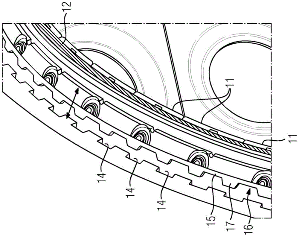
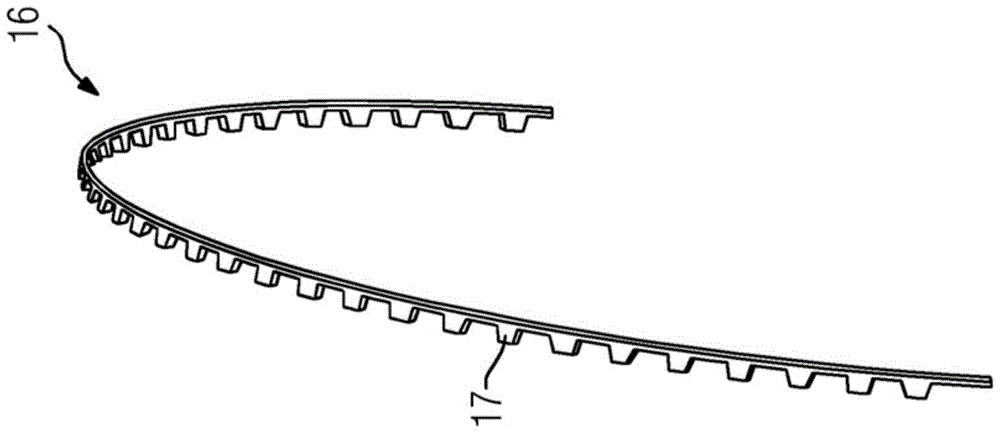
[0024] According to the invention, the combustion chamber casing 12 is provided with a channel in the region of the outlet 7 between the last ceramic heat shield row 13 (ie the penultimate heat shield row) and the metallic inlet shell ...
PUM
 Abstract
Description
Claims
Application Information
 - R&D Engineer
- R&D Manager
- IP Professional
- Industry Leading Data Capabilities
- Powerful AI technology
- Patent DNA Extraction
Browse by: Latest US Patents, China's latest patents, Technical Efficacy Thesaurus, Application Domain, Technology Topic, Popular Technical Reports.
© 2024 PatSnap. All rights reserved.Legal|Privacy policy|Modern Slavery Act Transparency Statement|Sitemap|About US| Contact US: help@patsnap.com


