
Heat shield element for compressed air bypass around combustion chamber

A heat shield, combustor technology, applied in the field of combustors, to solve problems affecting gas turbine power, etc.

Inactive Publication Date: 2016-03-02
SIEMENS AG
View PDF6 Cites 0 Cited by
  • Summary
  • Abstract
  • Description
  • Claims
  • Application Information

AI Technical Summary

Problems solved by technology

The difficulty here is that the bypass should only be activated in the relevant power range, since otherwise the power of the gas turbine would be affected unnecessarily

Method used


Image

  • Heat shield element for compressed air bypass around combustion chamber
  • Heat shield element for compressed air bypass around combustion chamber
  • Heat shield element for compressed air bypass around combustion chamber

Examples


Embodiment Construction

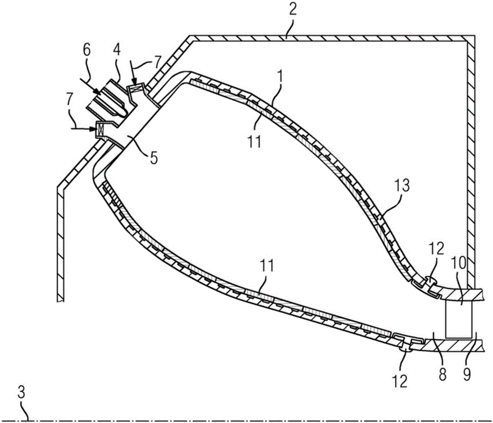
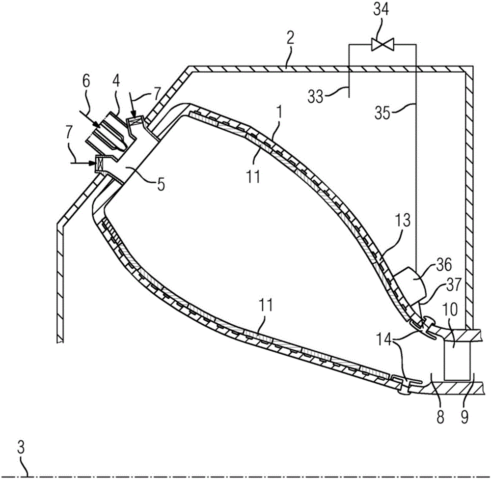
[0026] figure 1 The combustion system of an annular combustion chamber 1 according to the prior art is shown schematically and by way of example in a housing 2 . The annular combustion chamber 1 , which is formed as a closed ring, is arranged around the axis of rotation 3 . The burner 4 is arranged in the inlet 5 in the upper region of the combustion chamber 1 . There, fuel 6 is mixed with compressed air 7 . Combustion itself takes place in the combustion chamber 1 . The hot combustion gases enter the turbine 9 through an outlet at the turbine-side end of the annular combustion chamber 1 , where they come into contact with the first blades 10 . For protection prior to ignition, the annular combustion chamber 1 is lined with ceramic heat shield elements 11 and metal heat shield elements 12 , which are fastened to the combustion chamber wall 13 .

[0027] According to the invention, the introduction of the bypass air should be carried out in the region of the metal heat shie...


PUM


Abstract

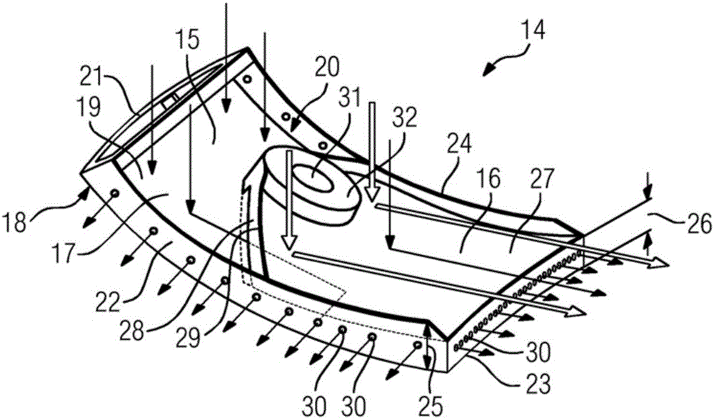
The invention relates to a heat shielding element (14), in particular for lining a combustion chamber wall (13), comprising a first wall (17) having a hot side capable of being loaded with a heat medium ( 18), the cold side (19) opposite to the hot side (18) and the surrounding edge (24), the surrounding edge (24) is on the first (20), second (21) of the first wall (17) And the third narrow side (22) protrudes from the cold side (19) and extends substantially to the first height (25), wherein the surrounding edge (24) extends on the fourth narrow side (23) to a height greater than the first height (25). a second height (26) lower than the height (25), and the second wall (27) extends approximately at the second height (26) relative to the cold side (19) and over the width of the fourth narrow side (23) , extending from the fourth narrow side (23) over a portion of the length of the narrow sides (20, 22) adjacent to the fourth narrow side (23), wherein the second wall (27) is facing away from the fourth narrow side The side (23) has an edge (29) on its end, which edge (29) extends to a first height (25). The invention also relates to a combustor and a gas turbine.

Description

technical field [0001] The invention relates to a heat shielding element for a combustion chamber of a gas turbine, in particular an annular combustion chamber, and to a bypass of compressed air around the combustion chamber during part-load operation. The invention also relates to a combustor and a corresponding gas turbine installation. Background technique [0002] As a result of the reduction in the core flame temperature when the output of the gas turbine is reduced, the carbon monoxide emissions gradually increase until they exceed the legal emission limit values ​​at certain partial loads. Thus, there is an admissible minimum power. But importantly, the machine has been able to keep working on extremely low power. [0003] A possibility to increase the flame temperature and thereby reduce carbon monoxide emissions is to route a portion of the compressed air around the combustion and again to the hot gas path before entering the turbine. Calculations show that this ...

Claims


Application Information

Patent Timeline
Patent Type & Authority Patents(China)
IPC IPC(8): F23R3/00F23M5/00
CPCF23R3/005F23R3/007F23R2900/03042F23R3/60F23R3/08F23R3/06F23R3/50
Inventor F.本克勒T.布兰登堡O.戴斯T.格里布M.林克N.萨维利厄斯D.沃格特曼J.威尔克斯
Owner SIEMENS AG
Learn More