
Precision Peeler

A peeling machine, precise technology, applied in the direction of electrical components, disassembly/armoured cable equipment, circuits, etc., can solve the problems of large volume occupying production space, heavy handling and safety hazards, peeling size cannot be fool-proof, etc. Achieve the effects of improving the production environment, increasing product profits, and reducing machine costs

Active Publication Date: 2016-03-02
FUJIAN J K WIRING SYST
View PDF5 Cites 0 Cited by
  • Summary
  • Abstract
  • Description
  • Claims
  • Application Information

AI Technical Summary

Problems solved by technology

Since the current terminal machine is not foolproof for the peeled size and has no protection measures for the core wire, there are safety hazards in the handling when changing the wire, the large volume occupies the production space, the machine is noisy and the cost of the terminal machine is high.

Method used


Image

  • Precision Peeler

Examples


Embodiment Construction

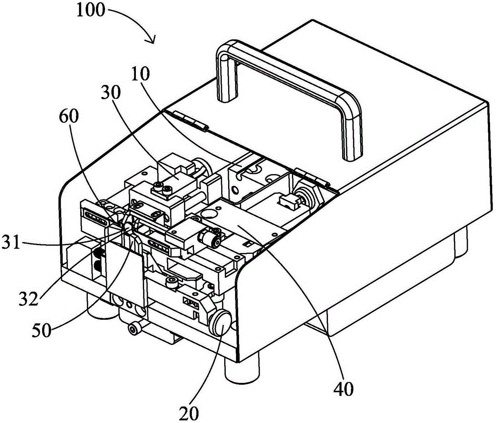
[0015] see figure 1 As shown, the precision peeling machine 100 of the present invention is used to peel the cables (not shown), which includes a cylinder 10, a screw adjustment knob 20, a precision photoelectric sensor 30, a double timing cam mechanism 40, and a cable positioning pressing block 50 and a pair of blades 60 spaced apart left and right.

[0016] The cylinder 10 is connected with the cam mechanism 40 via a floating joint. The cam mechanism 40, the cable positioning briquetting block 50 and the blade 60 are connected as a whole, the screw adjusting knob 20 is installed on the cam mechanism 40, the precision photoelectric sensor 30 is fixed above the screw adjusting knob 20, and a limit sensing PIN needle 31 and a limit sensor pin 31 are provided. Two fool-proof limit blocks 32 in front of the position sensing PIN needle 31, the limit sensing PIN pin 31 is used to control its induction and adjust the peeling size, and the blade 60 cuts off the cable sheath accordin...


PUM


Abstract

The invention relates to a precision skinning machine, for peeling a cable. The precision skinning machine comprises a cylinder, a screw adjusting knob, a precision photoelectric sensor, a double-sequence cam mechanism, a cable positioning pressure block and a blade. The cylinder and the cam mechanism are connected by means of a floating joint; the cam mechanism, the cable positioning pressure block and the blade are connected to form one body; the precision photoelectric sensor is fixed above the screw adjusting knob and is provided with a limiting induction pin and a foolproof limiting barrier sheet disposed in front of the limiting induction pin; the limiting induction pin is used for controlling induction so as to adjust peeling dimension; and the blade can, according to the time sequence of the cam mechanism, cut off the skin of the cable, then returns to spare 0.2 mm and perform peeling to protect a core wire.

Description

technical field [0001] The invention relates to a cable processing machine, in particular to a precision peeling machine. Background technique [0002] At present, in the process of round strand wire harness processing, terminal machines are mostly used for peeling that requires precision (the core wire is not allowed to be scratched or broken). Since the current terminal machine is not fool-proof for the peeled size and has no protection measures for the core wire, there are safety hazards in the handling when changing the wire, the large volume occupies the production space, the machine is noisy and the cost of the terminal machine is high. [0003] Therefore, it is necessary to improve the above technical problems. Contents of the invention [0004] The object of the present invention is to provide a precision peeling machine with improved product quality. [0005] In order to achieve the aforementioned purpose, the present invention adopts the following technical sol...

Claims


Application Information

Patent Timeline
Patent Type & Authority Patents(China)
IPC IPC(8): H01R43/28H02G1/12
Inventor 唐为军夏荣华李兴标葛新华郭飞
Owner FUJIAN J K WIRING SYST
Learn More