
Waveguide mode converter

A technology of mode converter and waveguide, which is applied in the direction of optical waveguide and light guide, can solve the problems of difficult processing of waveguide mode converters, and achieve the effects of easy processing, small size and high application value

Inactive Publication Date: 2014-11-26
PEKING UNIV
View PDF0 Cites 16 Cited by
  • Summary
  • Abstract
  • Description
  • Claims
  • Application Information

AI Technical Summary

Problems solved by technology

[0003] The invention provides a waveguide mode converter to solve the technical problem of difficult processing of the waveguide mode converter in the prior art

Method used


Image

  • Waveguide mode converter
  • Waveguide mode converter
  • Waveguide mode converter

Examples


Embodiment Construction

[0034] In order to make the purposes, technical solutions and advantages of the embodiments of the present invention clearer, the technical solutions in the embodiments of the present invention will be clearly and completely described below with reference to the accompanying drawings in the embodiments of the present invention. Obviously, the described embodiments These are some embodiments of the present invention, but not all embodiments. Based on the embodiments of the present invention, all other embodiments obtained by those of ordinary skill in the art without creative efforts shall fall within the protection scope of the present invention.

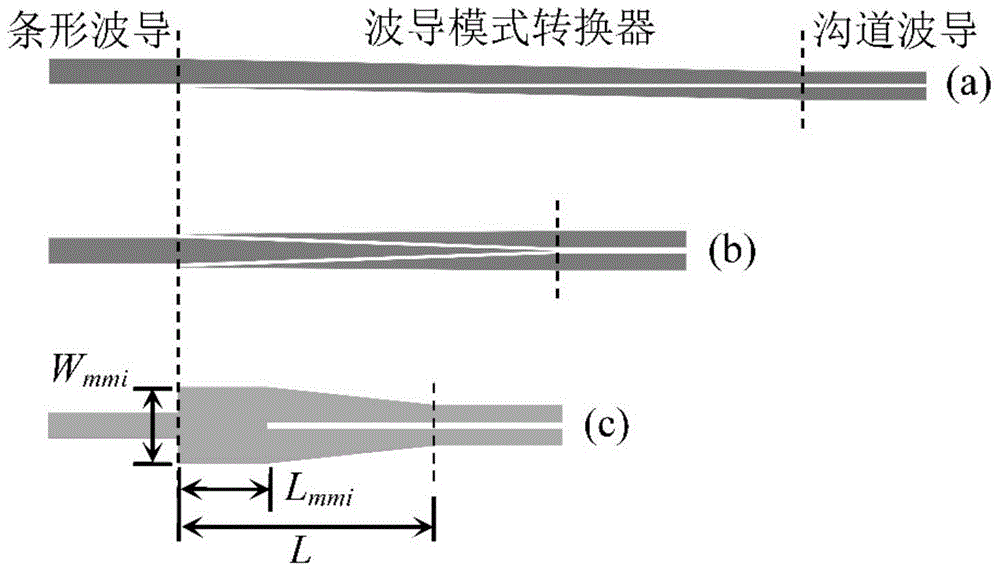
[0035] figure 2 A schematic structural diagram of a waveguide mode converter in an embodiment of the present invention is shown, see figure 2 , the waveguide mode converter in the embodiment of the present invention includes:

[0036] A multimode waveguide region 2 and a channel waveguide region 3 with a tapered width, one end o...


PUM


Abstract

The invention provides a waveguide mode converter which comprises a multimode waveguide area (2) and a channel waveguide area (3) with the width changing gradually, wherein one end of the multimode waveguide area (2) is used for being connected with a slab waveguide (1), the other end of the multimode waveguide area (2) is connected with one waveguide end face of the channel waveguide area (3) with the width changing gradually, the other waveguide end face of the channel waveguide area (3) with the width changing gradually is used for being connected with a channel waveguide (4), and channels in the channel waveguide area (3) with the width changing gradually correspond to channels of the channel waveguide (4) in a one-to-one mode. The waveguide mode converter has the advantages of being small in size, high in conversion efficiency, large in work bandwidth, high in technological tolerance and easy to machine and has high application value in the integrated photoelectron field.

Description

technical field [0001] The invention relates to the field of integrated optoelectronic devices, in particular to a waveguide mode converter. Background technique [0002] The slot waveguide can confine the optical field energy in the low refractive index medium (channel region), so it has many applications in the field of integrated optoelectronic devices, such as thermally stable microring resonator (athermal microring resonator), polarization separation Functional devices such as polarization beam splitters, optical amplifiers, nonlinear optical devices, and high performance electro-optic modulators. However, compared with the strip waveguide (~2dB / cm), the channel waveguide has a larger loss (~10dB / cm) when conducting the optical field, so the channel waveguide is usually used as an auxiliary structure in the integrated optoelectronic device system. , used only in the functional area of ​​the device. The strip waveguide is used as the basic structure to conduct the ligh...

Claims


Application Information

Patent Timeline
Patent Type & Authority Applications(China)
IPC IPC(8): G02B6/14
CPCG02B6/14
Inventor 周治平邓清中
Owner PEKING UNIV
Learn More