
Computerized flat knitting machine yarn feeder and yarn detection control system thereof

A computerized flat knitting machine and yarn feeder technology, applied in textiles and papermaking, weft knitting, knitting, etc., can solve problems such as difficult control of yarn tension and easy yarn breakage, achieve uniform and stable yarn feeding, and prevent jamming , The effect of reducing maintenance costs

Active Publication Date: 2014-11-26
QUANZHOU JINGZHUN MACHINERY
View PDF11 Cites 5 Cited by
  • Summary
  • Abstract
  • Description
  • Claims
  • Application Information

AI Technical Summary

Problems solved by technology

[0003] In the prior art, as a yarn feeder, such as the yarn feeder structure disclosed in Chinese patent document CN2275102Y, it essentially serves as a yarn storage function. However, in actual use, the yarn feeding method of this yarn feeder is passive feeding. Yarn, it is difficult to control the tension of the yarn, and some yarns are easy to break

Method used


Image

  • Computerized flat knitting machine yarn feeder and yarn detection control system thereof
  • Computerized flat knitting machine yarn feeder and yarn detection control system thereof
  • Computerized flat knitting machine yarn feeder and yarn detection control system thereof

Examples


Embodiment 1

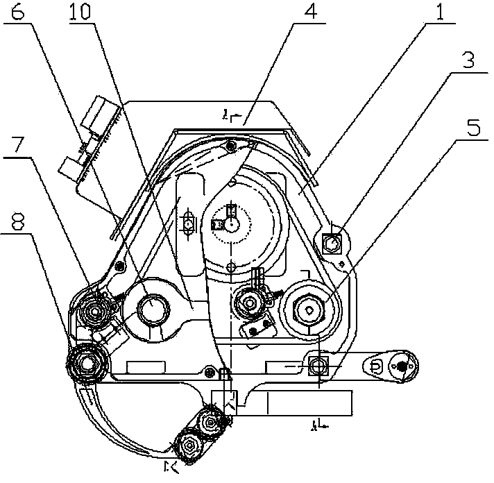
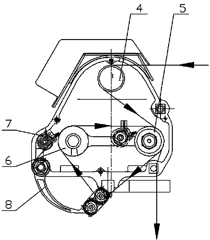
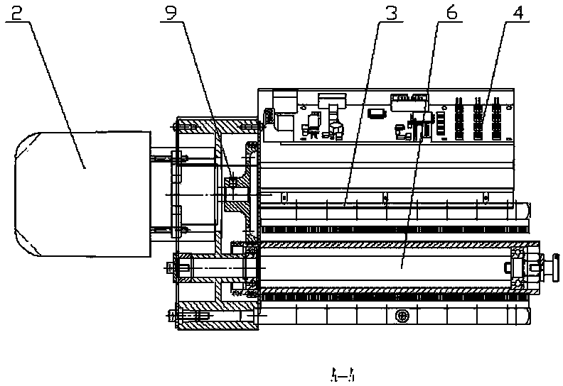
[0026] refer to Figure 1-Figure 9 , a computerized flat knitting machine yarn feeder, comprising a box body 1, a drive motor 2 installed outside the box body, a yarn guide rod 3, an encoder 4 assembled on the box body, a first yarn feed roller 5, a second yarn feeder Yarn roller 6, wax removal device 7 and adjustment device 8, and encoder 4 are connected to the computer, which can be used to measure the yarn speed and length, realize the stitch control of yarn feeding, and store data, suitable for different types of yarn, easy to use , the drive motor 2 drives the first yarn delivery roller 5 and the second yarn delivery roller 6 to rotate through the yarn delivery pulley 9, and the first yarn delivery roller 5 and the second yarn delivery roller 6 are connected by a connecting plate 10 and parallel Set, the side of the first yarn delivery roller 5 and the second yarn delivery roller 6 are respectively provided with a wax removal device 7, the wax removal device 7 is composed...

Embodiment 2

[0030] refer to Figure 1-Figure 9 , a computerized flat knitting machine yarn feeder, comprising a box body 1, a drive motor 2 installed outside the box body, a yarn guide rod 3, an encoder 4 assembled on the yarn guide rod, a first yarn feed roller 5, a second The yarn feeding roller 6, the wax removal device 7 and the adjustment device 8, the encoder 4 is connected with the computer, and can be used to measure the yarn speed and length, realize the stitch control of the yarn feeding, and store the data, which is suitable for different types of yarns. Conveniently, the drive motor 2 drives the first yarn delivery roller 5 and the second yarn delivery roller 6 to rotate through the yarn delivery pulley 9, and the first yarn delivery roller 5 and the second yarn delivery roller 6 are connected by a connecting plate 10, and Arranged in parallel, the sides of the first yarn delivery roller 5 and the second yarn delivery roller 6 are respectively provided with a wax removal devic...

Embodiment 3

[0033] refer to Figure 1-Figure 9 , a computerized flat knitting machine yarn feeder, comprising a box body 1, a drive motor 2 installed outside the box body, a yarn guide rod 3, an encoder 4 assembled on the box body, a first yarn feed roller 5, a second yarn feeder Yarn roller 6, wax removal device 7 and adjustment device 8, and encoder 4 are connected to the computer, which can be used to measure the yarn speed and length, realize the stitch control of yarn feeding, and store data, suitable for different types of yarn, easy to use , the drive motor 2 drives the first yarn delivery roller 5 and the second yarn delivery roller 6 to rotate through the yarn delivery pulley 9, and the first yarn delivery roller 5 and the second yarn delivery roller 6 are connected by a connecting plate 10 and parallel Set, the side of the first yarn delivery roller 5 and the second yarn delivery roller 6 are respectively provided with a wax removal device 7, the wax removal device 7 is composed...


PUM


Abstract

The invention discloses a computerized flat knitting machine yarn feeder and a yarn detection control system of the computerized flat knitting machine yarn feeder. The computerized flat knitting machine yarn feeder comprises a box, a driving motor, a yarn guide rod, an encoder, a first yarn feeding roller, a second yarn feeding roller, paraffin removal devices and an adjusting device, wherein the driving motor is installed outside the box. The driving motor drives the first yarn feeding roller and the second yarn feeding roller to rotate through a yarn feeding belt wheel, the first yarn feeding roller and the second yarn feeding roller are connected in parallel through a connecting plate, the side face of the first yarn feeding roller and the side face of the second yarn feeding roller are provided with the paraffin removal devices respectively, the paraffin removal devices are composed of anti-caking rods and brushes, the brushes fixedly adhere to the corresponding anti-caking rods, and the adjusting device forms a swing arm type adjusting structure through a rotatable fixing supporting point, ceramic wheel carriers and two movable ceramic wheel sets installed on fixing blocks. The computerized flat knitting machine yarn feeder is provided with the encoder, the speed and the length of yarn can be measured, stitches can be adjusted, yarn feeding is uniform and stable, the paraffin removal devices and the adjusting device are arranged, paraffin on the surfaces of the yarn feeding rollers is removed in time, service life is prolonged, and knitting efficiency and knitting quality are effectively improved.

Description

technical field [0001] The invention relates to the technical field of manufacturing computerized flat knitting machine yarn feeding devices, in particular to a computerized flat knitting machine yarn feeding device and a yarn detection and control system thereof. Background technique [0002] Computerized flat knitting machine is a kind of weft knitting loom. Its cam device is like a set of plane cams. The stitches of the knitting needles can enter the grooves of the cams, and the cams can be moved to force the knitting needles to move up and down regularly in the needle grooves of the needle plate. Movement, and through the action of the needle hook and latch, the yarn can be knitted into a knitted fabric. In the process of yarn feeding or yarn feeding, the existing yarn feeder feeds the yarn according to the friction between the yarn and the surface of the yarn feeding roller when transferring the yarn. Because different yarns have different elasticity, the friction coeff...

Claims


Application Information

Patent Timeline
IPC IPC(8): D04B15/38D04B35/10
Inventor 黄文才
Owner QUANZHOU JINGZHUN MACHINERY
Learn More