Motor control device
A control device and motor technology, applied in the direction of motor control, AC motor control, AC motor acceleration/deceleration control, etc., to achieve the effect of reducing power consumption
- Summary
- Abstract
- Description
- Claims
- Application Information
AI Technical Summary
Problems solved by technology
Method used
Image
Examples
Embodiment approach 1
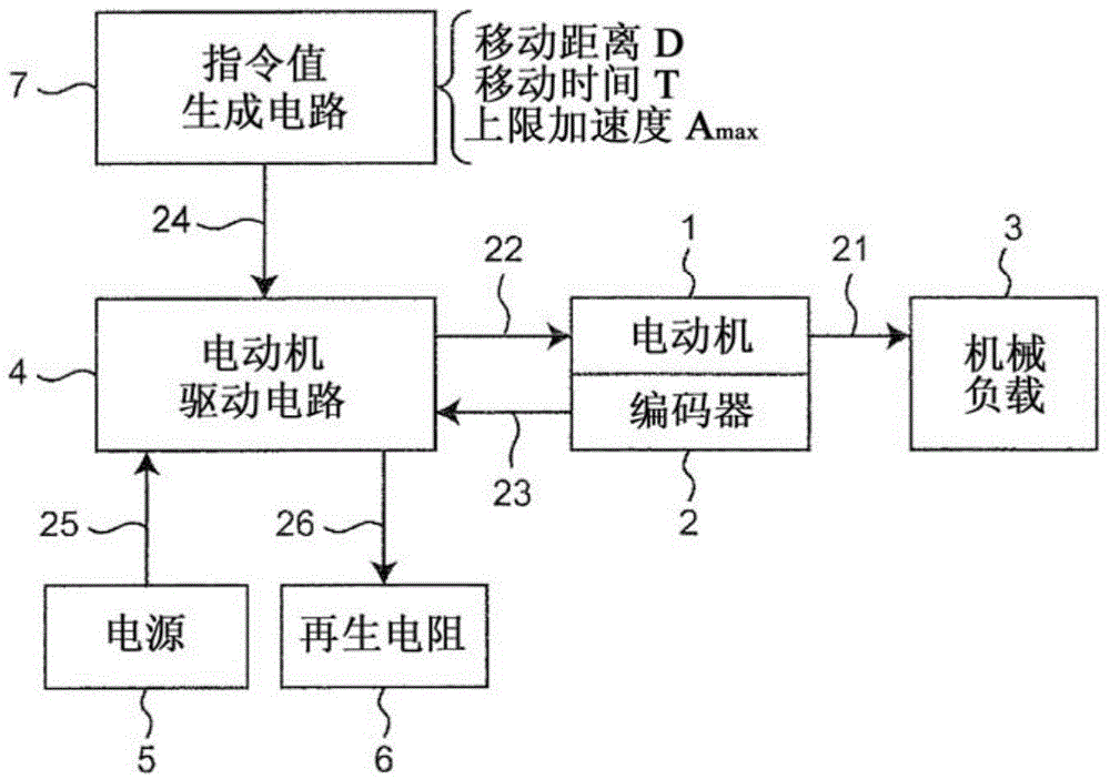
[0054] figure 1 It is a block diagram showing the configuration of a positioning system including the motor control device according to Embodiment 1 of the present invention. exist figure 1 In the positioning system, the motor control device includes a command value generation circuit 7, a motor drive circuit 4, and a regenerative resistor 6, and controls the motor 1 so that the mechanical load 3 connected to the motor 1 moves from the initial position (the first position) to the Target position (2nd position). figure 1 The positioning system also has a power supply 5 and an encoder 2.
[0055] The electric motor 1 operates with a current 22 supplied from the motor drive circuit 4 , and applies a driving force 21 such as torque or thrust to the mechanical load 3 . As the mechanical load 3, for example, a ball screw mechanism is assumed, but it is not limited thereto. The encoder 2 detects motor information 23 such as the rotational position (angle) and rotational speed of ...
Embodiment approach 2
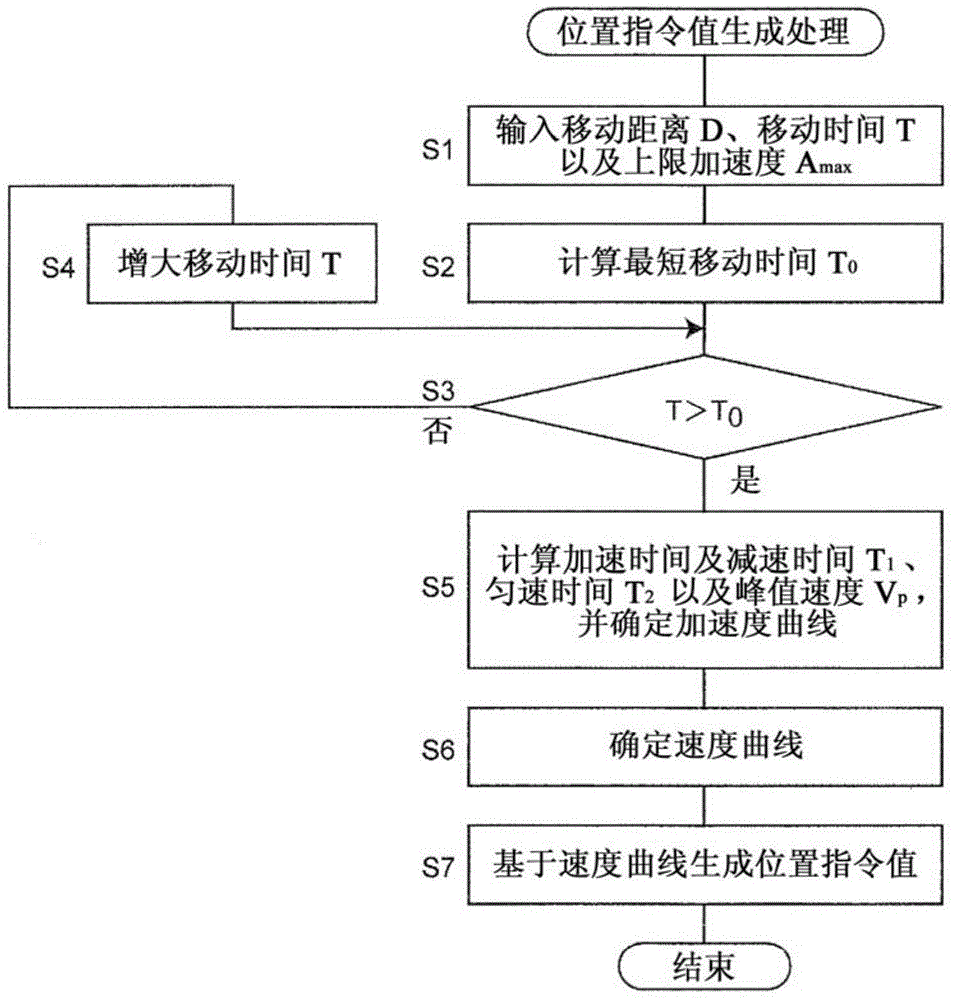
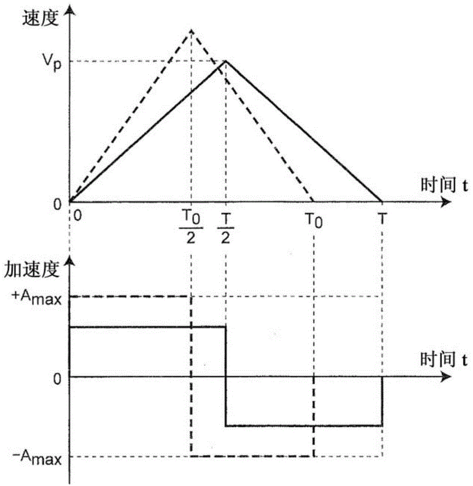
[0125] In Embodiment 1, positioning control is performed based on a trapezoidal speed profile in order to reduce power consumption. However, in this embodiment, a different speed profile is used. Although the configuration of the positioning system including the motor control device according to the second embodiment is the same as that of the first embodiment ( figure 1 ) are the same, however, the position command value generation process performed by the command value generation circuit 7 is different from that of the first embodiment.
[0126] Figure 6 It is a flowchart showing position command value generation processing according to Embodiment 2 of the present invention. exist Figure 6 In the flow chart of , since steps S1-S4 are similar to Embodiment 1 ( figure 2 ) are the same, so the explanation is omitted. When step S4 is yes, go to step S11. In step S11, it is determined whether the moving time T is shorter than the shortest moving time T 0 of times small...
Embodiment approach 3
[0205] In Embodiments 1 and 2, the effect was described by quantitatively calculating the power consumption when performing positioning control and showing its reduction. In the present embodiment, effects will be described using a different method. Although the configuration of the positioning system including the motor control device according to the third embodiment is the same as that of the first embodiment ( figure 1 ) are the same, however, the position command value generation process performed by the command value generation circuit 7 is different from that of the first embodiment.
[0206] Figure 11 It is a flowchart showing position command value generation processing according to Embodiment 3 of the present invention. exist Figure 11 In the flow chart of , since steps S1-S4 are similar to Embodiment 1 ( figure 2 ) are the same, so the explanation is omitted. When it is determined as YES in step S4, go to step S21, and determine the acceleration curve A(t) i...
PUM
 Abstract
Description
Claims
Application Information
 - R&D
- Intellectual Property
- Life Sciences
- Materials
- Tech Scout
- Unparalleled Data Quality
- Higher Quality Content
- 60% Fewer Hallucinations
Browse by: Latest US Patents, China's latest patents, Technical Efficacy Thesaurus, Application Domain, Technology Topic, Popular Technical Reports.
© 2025 PatSnap. All rights reserved.Legal|Privacy policy|Modern Slavery Act Transparency Statement|Sitemap|About US| Contact US: help@patsnap.com


