Eureka AIR delivers breakthrough ideas for toughest innovation challenges, trusted by R&D personnel around the world.

Charging control device, device and POS terminal

A charging control and charger technology, applied in the fields of POS terminals, devices, and charging control methods, can solve the problems of high cost, many energy conversion times, and large energy loss, and achieve the effects of reducing output current and improving charging efficiency.

Active Publication Date: 2014-11-19
FUJIAN LANDI COMML EQUIP CO LTD
View PDF2 Cites 13 Cited by
  • Summary
  • Abstract
  • Description
  • Claims
  • Application Information

AI Technical Summary

Problems solved by technology

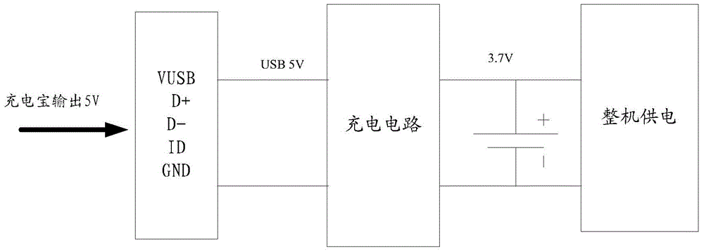
The integration of the charging device is low, requiring multiple ICs to complete the function, and the cost is high; at the same time, the number of energy conversions is large, the energy loss is large, and the efficiency is low

Method used


Image

  • Charging control device, device and POS terminal
  • Charging control device, device and POS terminal
  • Charging control device, device and POS terminal

Examples


Embodiment Construction

[0028] In order to describe the technical content, structural features, achieved goals and effects of the present invention in detail, the following will be described in detail in conjunction with the embodiments and accompanying drawings.

[0029] The most critical idea of ​​the present invention is to fully utilize the charging efficiency of the charger by actively adjusting the output current of the charger and monitoring the output voltage drop of the charger.

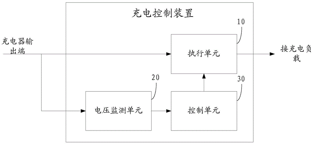
[0030] see image 3 , a charging control device, comprising a voltage monitoring unit 20, a control unit 30 and an execution unit 10;

[0031] The voltage monitoring unit 20 and the execution unit 10 are respectively connected to the output terminal of the charger and the control unit 30;

[0032] The control unit 30 is used to control the execution unit 10 to increase or decrease the output current of the charger;

[0033] The voltage monitoring unit 20 is used to judge whether the output voltage drop value of t...


PUM


Abstract

The invention discloses a charging control device. The charging control device comprises a voltage monitoring unit, a control unit and an execution unit, wherein the voltage monitoring unit and the execution unit are connected to the output end of a charger and the control unit respectively; the control unit is used for controlling the execution unit to increase or decrease the output current of the charger; the voltage monitoring unit is used for judging whether the drop value of the output voltage of the charger is greater than a preset threshold value and sending judging results to the control unit; the control unit is used for controlling the execution unit to decrease the output current of the charger when the drop value of the output voltage of the charger is greater than the preset threshold value; when the drop value of the output voltage of the charger is less than or equal to the preset threshold value, the control unit controls the execution unit to increase the output current of the charger. The invention further discloses a charging control method and a POS terminal of the charging control device. According to the charging control device provided by the invention, the charging efficiency of the charger can be effectively improved.

Description

technical field [0001] The invention relates to the field of charging electronic equipment, in particular to a charging control method and device and a POS terminal. Background technique [0002] Mobile power supply, English mobile power pack (abbreviated as MPP), a portable charger that integrates power supply and charging functions, can charge mobile phones and other digital devices anytime, anywhere or standby power. Lithium batteries or dry batteries are generally used as power storage units. The battery that is different from the internal configuration of the product is also called an external battery. It is generally equipped with a variety of power adapters, which usually have the characteristics of large capacity, multi-purpose, small size, long life and safety and reliability. It can be used for mobile phones, digital cameras, MP3, MP4, PDA, handheld computers, handheld game consoles, etc. Functional products for power supply or standby charging of various digital...

Claims


Application Information

Patent Timeline
Patent Type & Authority Applications(China)
IPC IPC(8): H02J7/00
CPCH02J7/00
Inventor 胡利国
Owner FUJIAN LANDI COMML EQUIP CO LTD
Why Eureka
Eureka Blog
Learn More