
Current measuring device based on combined PCB type Rogowski coils and method thereof

The technology of a current measuring device and Rogowski coil is applied in the direction of measuring device, measuring electrical variables, measuring current/voltage, etc., which can solve the problems of unfavorable large-scale industrial production, low measurement accuracy and stability, and large dispersion of product performance. , to achieve the effect of easy mass production, strong anti-interference ability and low production cost

Inactive Publication Date: 2014-11-19
STATE GRID CORP OF CHINA +1
View PDF6 Cites 23 Cited by
  • Summary
  • Abstract
  • Description
  • Claims
  • Application Information

AI Technical Summary

Problems solved by technology

[0004] The purpose of the present invention is to provide a current measuring device and method based on a combined PCB type Rogowski coil, which solves the problem that the measurement accuracy and stability of the traditional Rogowski coil are not high, the production is troublesome, and the product performance is highly dispersed, which is not conducive to The problem of large-scale industrial production

Method used


Image

  • Current measuring device based on combined PCB type Rogowski coils and method thereof
  • Current measuring device based on combined PCB type Rogowski coils and method thereof
  • Current measuring device based on combined PCB type Rogowski coils and method thereof

Examples


Embodiment Construction

[0033] The technical solutions in the embodiments of the present invention will be clearly and completely described below in conjunction with the accompanying drawings of the present invention. Obviously, what is described here is only a part of the examples of the present invention, not all examples. Based on the implementation of the present invention For example, all other embodiments obtained by persons of ordinary skill in the art without making creative efforts belong to the protection scope of the present invention.

[0034] In order to facilitate the understanding of the embodiments of the present invention, specific embodiments will be taken as examples for further explanation below in conjunction with the accompanying drawings, and each embodiment does not constitute a limitation to the embodiments of the present invention.

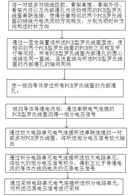
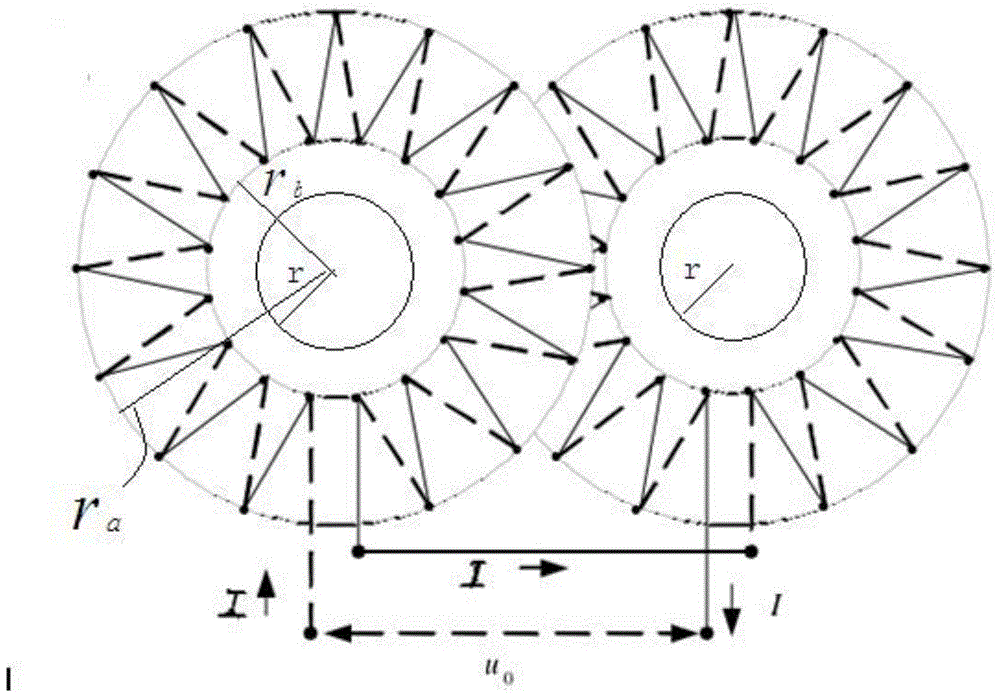
[0035] as attached Figure 1-5 A current measurement device based on a combined PCB type Rogowski coil is shown, which measures a conducting cu...


PUM


Abstract

The invention relates to a current measuring device based on combined PCB type Rogowski coils and a method thereof. The device comprises one or more pairs of PCB type Rogowski coils, an amplifier circuit unit, an integral circuit unit and a sampling circuit unit. One or more pairs of PCB Rogowski coils orderly are connected in series. The directions of current flow in the winding wires of any two adjacent PCB Rogowski coils are opposite. Through holes in the PCB Rogowski coils pass through conductors with the conduction of current, and differential voltage signals are measured. The one or more pairs of PCB type Rogowski coils in series connection are electrically connected to the amplifier circuit unit. The amplifier circuit unit amplifies and outputs the differential voltage signals. The integral circuit unit integrates the amplified differential voltage signals to obtain reducing voltage signals which are proportional to the measured current in the conductors with the conduction of current. The sampling circuit unit samples the reducing voltage signals. The device and the method have the advantages of good parameter consistence and high reproducibility, and stability of a mutual inductance coefficient is ensured.

Description

technical field [0001] The invention relates to a current measuring device and method, in particular to a current measuring device and method based on a combined PCB type Rogowski coil. Background technique [0002] With the improvement of the operating voltage of the power grid and the improvement of reliability requirements, the traditional electromagnetic transformer not only increases in volume and weight, difficulty in explosion-proof insulation, and decline in safety performance, but also narrows the frequency band due to the existence of the iron core. The iron core will be saturated, which will cause serious distortion of the secondary signal waveform, and the dynamic range is small. When used as a relay protection, the response speed is lagging and it is easy to cause malfunction. This series of shortcomings has made it difficult for traditional electromagnetic transformers to meet the requirements of power system development. Moreover, the traditional electromagne...

Claims


Application Information

Patent Timeline
Patent Type & Authority Applications(China)
IPC IPC(8): G01R19/00
Inventor 李晓博李志清朱晓彬郑益慧李立学王昕苏彪
Owner STATE GRID CORP OF CHINA
Learn More