Gas content desorption testing device

A measuring device and technology for gas content, which are applied in the field of petroleum exploration, can solve the problems of inability to use manual measurement, fail to realize automation, affect measurement results, etc., and achieve the effects of moderate volume, improved measurement efficiency, and accurate and reliable data.

Active Publication Date: 2014-11-19
CHINA PETROLEUM & CHEM CORP +1
View PDF10 Cites 5 Cited by
  • Summary
  • Abstract
  • Description
  • Claims
  • Application Information

AI Technical Summary

Problems solved by technology

[0003] Taking shale gas as an example, there are currently two types of instruments used for on-site desorption measurement of shale gas: one is a shale gas on-site desorption measuring instrument with a mass flow meter as the measurement method, and this type of instrument can realize automatic measurement , but because the gas composition is required to be single or constant when measuring the volume of mass flow flow, different gases need to be converted to get the real volume of the gas flowing through the flowmeter, and when the gas contains water vapor, the measured value will be There will be a large deviation. For the on-site desorption gas measurement of shale, its components will also change with the desorption time. The core will inevitably contain a certain amount of water, which also directly affects the measurement results.
If there is a power outage, he cannot use manual metering
The second method is to use the traditional drainage and gas collection method for measurement. When reading, it is necessary to manually move the container containing water to the vicinity of the metering glass tube, and use the naked eye to align the water level before reading.
After a tube of core comes out, it is generally necessary to take more than 3-4 samples. Since the measurement period of the on-site desorption amount is the shortest, a number needs to be read every 2 minutes, and someone must take readings at any time at night, so the workload is very heavy, and it is not possible. Realize automation, and when the glass tube is filled with gas, it is impossible to switch the measurement

Method used


Image

  • Gas content desorption testing device

Examples


Embodiment Construction

[0025] The present invention will be further described below in conjunction with the accompanying drawings and embodiments, but this does not constitute any limitation to the present invention.

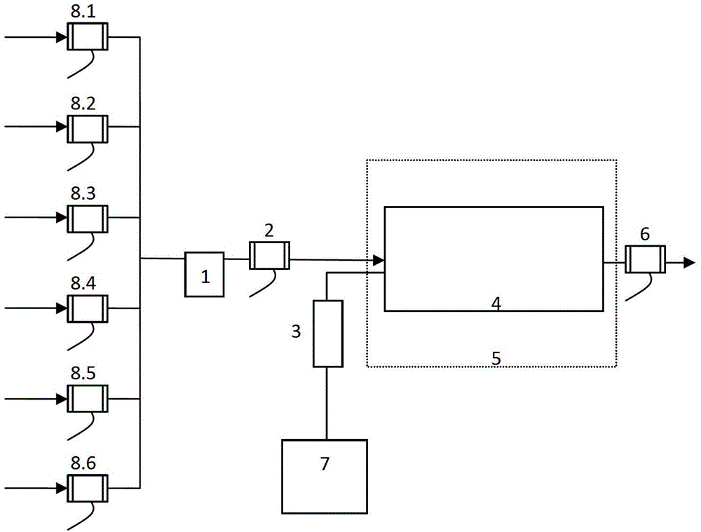
[0026] figure 1 A schematic diagram of an embodiment according to the invention is shown. In the figure, reference numerals 8.1-8.6 are first solenoid valves, which are respectively connected to different desorption gas sources. In a specific embodiment, the rock sample in the desorption tank is used as the desorption gas source. The first solenoid valves 8.1-8.6 are connected in parallel. The gas-water separation device 1 connected with the first electromagnetic valve 8.1-8.6. In a specific embodiment, the gas-water separation device 1 is a gas-water separator. The second solenoid valve 2 is connected with the gas-water separation device 1 . The second solenoid valve 2 is used for timing opening to allow gas to enter the container. The gas container 4 is connected with the seco...


PUM


Abstract

The invention discloses a gas content desorption testing device. The device comprises a first solenoid valve connected with a desorption gas source, a gas and water separation device connected with the first solenoid valve, a second solenoid valve connected with the gas and water separation device, and a gas container connected with the second solenoid valve. The outlet of the gas container is equipped with a third solenoid valve. The gas container is equipped with a pressure measurement device. The pressure measurement device is connected with a data processing system. The first solenoid valve and the second solenoid valve are used for controlling gas inlet, and the third solenoid valve is used for controlling gas discharging. The method and the device can measure a gas volume directly and automatically, and can fit rock samples with different desorption amounts, and the acquisition period is short. The device is advantaged by small power consumption, simple operation and moderate volume, and is suitable for field on-site usage.

Description

technical field [0001] The invention relates to the field of petroleum exploration, in particular to a device for measuring the on-site desorption amount of shale gas, coal bed methane, etc. in unconventional oil and gas exploration. Background technique [0002] Shale gas and coalbed methane are natural gas that occurs in shale or coal rocks. In unconventional oil and gas exploration such as shale or coal seams, the content of shale gas and coalbed methane is directly related to the development prospects of shale gas and coalbed methane. It is necessary to effectively evaluate whether shale gas or coalbed methane has commercialization prospects in a certain area , it is necessary to establish accurate gas content data, which are used for gas reservoir simulation and production prediction. For this, the gas content and desorption properties of the shale core or coal core must be known. Therefore, shale gas / coalbed methane gas content testing equipment is very important for...

Claims


Application Information

Patent Timeline
IPC IPC(8): G01N7/14G01N1/28
Inventor 范明蒋启贵刘伟新俞凌杰张文涛王强陈红宇宋小莹
Owner CHINA PETROLEUM & CHEM CORP
Why Eureka
Try Eureka