
A valve core assembly for operating a valve group

A valve core assembly and control valve group technology, applied in the field of hydraulic components, can solve problems such as seal ring damage and valve core assembly failure, and achieve the effects of reducing contact area, improving sealing performance, improving sealing effect and service life

Active Publication Date: 2016-06-22
HONGDA INTELLIGENT MACHINERY CO LTD
View PDF7 Cites 0 Cited by
  • Summary
  • Abstract
  • Description
  • Claims
  • Application Information

AI Technical Summary

Problems solved by technology

The valve core is located inside the valve casing, and there is a sealing structure between the valve core and the valve casing, but because only a single O-ring seal is used between the valve core and the valve casing, the valve core moves back and forth, and the unloading on the valve core The small hole often rubs against the O-ring, which will easily damage the sealing ring, which will lead to the failure of the valve core assembly

Method used


Image

  • A valve core assembly for operating a valve group
  • A valve core assembly for operating a valve group
  • A valve core assembly for operating a valve group

Examples


Embodiment Construction

[0034] The specific embodiment of the present invention will be described in further detail by describing the embodiments below with reference to the accompanying drawings, the purpose is to help those skilled in the art to have a more complete, accurate and in-depth understanding of the concept and technical solutions of the present invention, and contribute to its implementation.

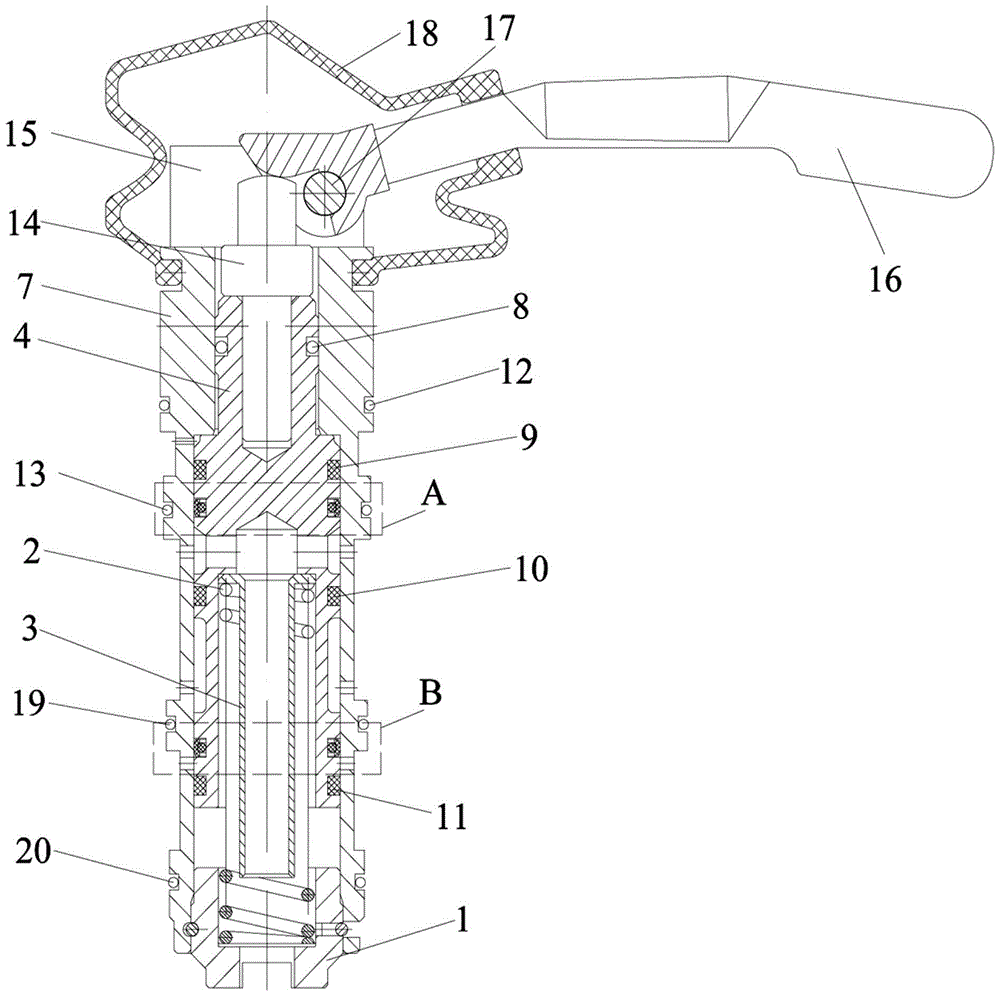
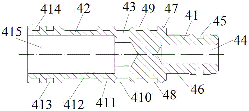
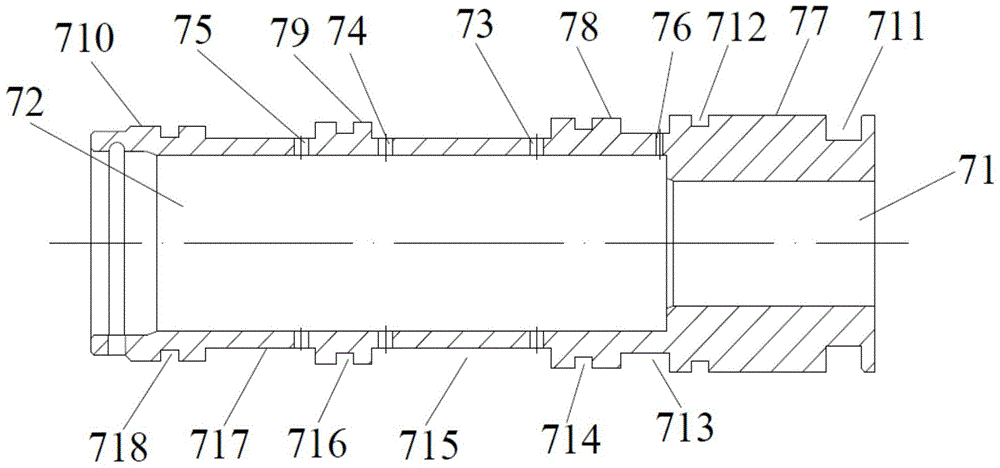
[0035] Such as Figure 1 to Figure 9 As shown, a spool assembly for manipulating a valve group in the present invention includes a valve housing 7 , a spool 4 , a pressing rod 14 , a spring seat 1 , a return spring 2 , a guide rod 3 and a handle 16 . The valve casing 7 is a cylindrical member with openings at both ends and a hollow interior. The spring seat 1 is inserted into the valve casing 7 at one end of the valve casing 7 and is fixedly connected with the valve casing 7. The valve core 4, the return spring 2 and the guide rod 3 are located in the valve Inside the housing 7, the pressure rod ...


PUM


Abstract

The invention discloses a valve core assembly for manipulating a valve group, which includes a valve casing and a valve core. A composite sealing structure is arranged between the valve core and the valve casing. The composite sealing structure includes an inner sealing ring and an outer sealing ring, and the outer sealing ring includes The inner peripheral surface, the outer peripheral surface coaxial with the inner peripheral surface, and the end faces on both sides of the inner peripheral surface and the outer peripheral surface, the outer sealing ring also includes two outer conical surfaces coaxial with the inner peripheral surface, two outer conical surfaces The surfaces are respectively connected to one end of the outer peripheral surface and an edge of an end surface. The spool assembly, through the outer conical surface set on the outer surface of the outer sealing ring, when the composite sealing structure moves with the valve core in the valve housing, on the one hand, it is convenient for the outer sealing ring to slide through the liquid hole on the valve housing, and on the other hand On the one hand, it can reduce the contact area with the liquid passage hole and reduce the wear of the outer sealing ring, thereby improving the sealing effect and service life of the composite sealing structure, and finally improving the sealing performance between the valve core and the valve housing.

Description

technical field [0001] The invention relates to a hydraulic component of a fully mechanized coal mining hydraulic support, in particular to a valve core assembly of a shearer control valve group. Background technique [0002] With the large-scale implementation and development of coal mine fully mechanized mining hydraulic supports, fully mechanized mining work has more and more stringent requirements for hydraulic supports, so there are further requirements for the safety valve of the hydraulic cylinder of the protection support, especially for the safety valve There are further requirements for the service life and reliability of the hydraulic support. When the pressure from the top of the hydraulic support causes passive force, whether the safety valve can unload in a short time, fully and stably under the condition of high pressure directly affects the service life of the support. and support security. It will not only damage seals, pipes and hydraulic components, but a...

Claims


Application Information

Patent Timeline
Patent Type & Authority Patents(China)
IPC IPC(8): E21D15/51E21D23/16
Inventor 李福洪朱述群
Owner HONGDA INTELLIGENT MACHINERY CO LTD
Learn More