
Automatic pipe discharging and feeding device

A technology of feeding device and automatic discharging, applied in the direction of automatic in/out of workpieces, metal processing machinery parts, metal processing, etc., can solve the problems of low work efficiency and high labor intensity.

Inactive Publication Date: 2014-11-19
旭东机械(昆山)有限公司
View PDF6 Cites 8 Cited by
  • Summary
  • Abstract
  • Description
  • Claims
  • Application Information

AI Technical Summary

Problems solved by technology

[0002] The existing technology often involves the processing of pipe fittings. It is necessary to place the pipe fittings at designated positions at continuous intervals to facilitate the processing of the pipe fittings. For example, before putting the pipe fittings on the inward-expanding elastic collet manually, the pipe fittings need to be placed manually until the processing of the pipe fittings is completed. Repeatedly place the pipe fittings again, the work efficiency is low and the labor intensity is high

Method used


Image

  • Automatic pipe discharging and feeding device
  • Automatic pipe discharging and feeding device
  • Automatic pipe discharging and feeding device

Examples


Embodiment Construction

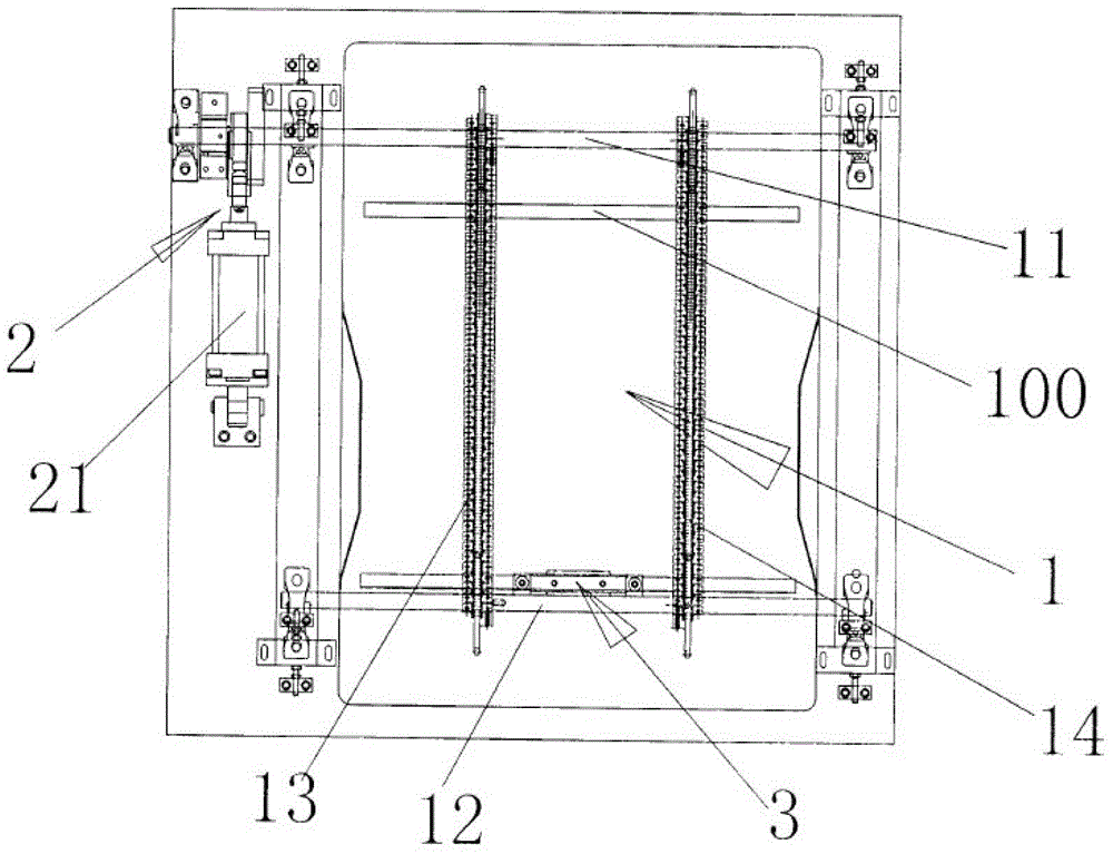
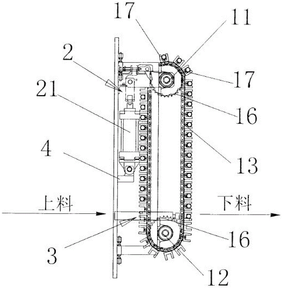
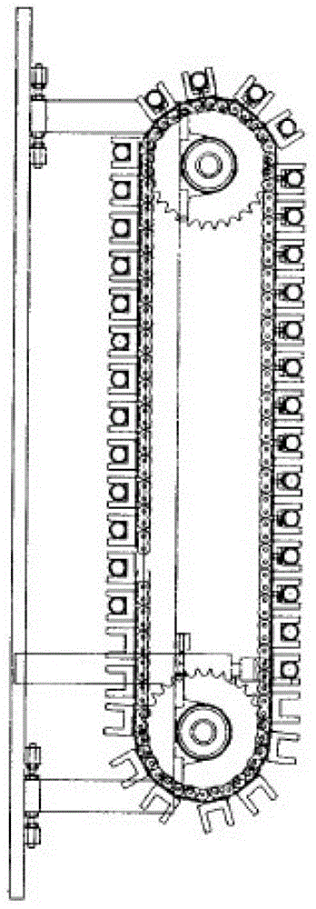
[0026] like figure 1 , figure 2 , image 3 and Figure 4 As shown, an automatic discharge and feeding device for pipe fittings includes a discharge mechanism 1 that can be embedded in a pipe fitting 100, a drive mechanism 2 that can drive the displacement of the pipe fittings on the discharge mechanism, and a device that can grab and transport the pipe fittings on the discharge mechanism. Feeding mechanism 3, wherein:

[0027] 1) The discharge mechanism 1 has two side-by-side chain rings 13, 14, and the two chain rings 13, 14 are jointly installed on two main shafts 11, 12 arranged side by side through a set of sprockets 16, and the two main shafts 11, 12 are vertically vertical Set, these two chain rings 13,14 respectively fix many pairs of pipe fitting clamping dies 17 that can be embedded in the same pipe fitting, and the multiple pairs of pipe fitting clamping dies 17 are evenly distributed on the two chain rings 13,14. The embedded notch, in order to facilitate the f...


PUM


Abstract

An automatic pipe discharging and feeding device comprises a discharging mechanism, a driving mechanism and a feeding mechanism, wherein pipes can be embedded in the discharging mechanism, the driving mechanism can drive the pipes on the discharging mechanism to move, and the feeding mechanism can grab and convey the pipes on the discharging mechanism. The discharging mechanism is provided with two chain rings arranged side by side, the two chain rings are installed on two spindles together through a set of chain wheels, the two spindles are arranged side by side, multiple pairs of pipe clamping dies are fixed to the two chain rings respectively, and one pipe can be embedded in the corresponding pair of pipe clamping dies. The driving mechanism is installed on one spindle and comprises a ratchet wheel, a pawl fixing plate and a driving air cylinder, wherein the ratchet wheel is fixed to the corresponding spindle, the corresponding spindle is movably sleeved with one end of the pawl fixing plate, the pawl fixing plate and the ratchet wheel are located side by side, and the driving air cylinder can drive the other end of the pawl fixing plate to swing in a reciprocating mode. The pawl fixing plate is further provided with a pawl, wherein the pawl can be meshed with the ratchet wheel in one direction and drive the ratchet wheel together with the spindle to rotate. The feeding mechanism comprises two supporting dies and a feeding air cylinder, wherein the feeding air cylinder can drive the two supporting dies to push out the pipes on the corresponding pipe clamping dies. According to the automatic pipe discharging and feeding device, the pipes can be placed continuously and conveyed out automatically, working efficiency is improved, and labor intensity is reduced.

Description

technical field [0001] The invention belongs to a pipe fitting processing device, in particular to a device capable of automatically discharging pipe fittings at intervals and automatically feeding materials at intervals. Background technique [0002] The existing technology often involves the processing of pipe fittings. It is necessary to place the pipe fittings at designated positions at continuous intervals to facilitate the processing of the pipe fittings. For example, before manually putting the pipe fittings on the inward-expanding elastic collet, the pipe fittings need to be manually placed until the pipe fittings are processed. Repeatedly place pipe fittings again, work efficiency is low and labor intensity is big. Contents of the invention [0003] In order to make up for the above shortcomings, the present invention provides an automatic discharge and feeding device for pipe fittings, which can continuously place pipe fittings at intervals and automatically send...

Claims


Application Information

Patent Timeline
Patent Type & Authority Applications(China)
IPC IPC(8): B23Q7/03
CPCB23Q7/03B23Q7/06B23Q2707/02
Inventor 刘家真
Owner 旭东机械(昆山)有限公司
Learn More