
Load measurement apparatus and methods utilizing torque sensitive link for pedal powered devices

a technology of torque sensitive link and measurement apparatus, which is applied in the direction of bicycle equipment, instruments, and hoisting equipment, can solve the problems of difficult to determine if any training progress has been made using only a heart rate monitor, difficult to gauge the intensity of cycling, and expensive devices such as these, which are difficult to install and maintain, and achieve accurate output and simple installation and maintenance.

Inactive Publication Date: 2005-08-18
FORZA
View PDF8 Cites 77 Cited by
  • Summary
  • Abstract
  • Description
  • Claims
  • Application Information

AI Technical Summary

Benefits of technology

[0007] This invention provides apparatus and methods for use in measurement of a cyclist's performance during a ride by measuring applied loads developed by the cyclist. The apparatus and methods provided are inexpensive, are aesthetically unobtrusive, require no modification of major components, utilizing the existing structure of a standard chainring assemblage (i.e., the existing spider and chainring or rings, unmodified), are simple to install and maintain, and provide accurate output. The apparatus and methods of this invention are adapted for use with many types of pedal powered devices utilized by cyclists, for example, velocipedes such as on and / or off road bicycles, tricycles and the like, and / or various similarly constructed fitness and training apparatus, both mobile and stationary, and may be referred to hereinafter for ease of description as “cycle(s)” for use by “cyclist(s)”, it being understood that the broader meaning is intended.
[0009] The apparatus itself includes a link adapted for interposition between one of the chainring mount attachment sites and a corresponding one of the chainring attachment locales. The link has a geometry and / or material composition selected to accommodate measurement of load exhibited between the attachment site and the chainring attachment locale. A preferred embodiment of the link has a first end adapted for connectability with the attachment site and a second end adapted for connectability with the corresponding attachment locale. A central portion of the link is configured to be resiliently load sensitive. In the preferred embodiment, the link is constructed of a durable material with a known modulus of elasticity thereby delivering a reliable and repeatable displacement with load.
[0012] It is another object of this invention to provide apparatus and methods for use in measurement of applied loads developed by a cyclist during a ride that are inexpensive, are aesthetically unobtrusive, require no modification of major components, utilize existing structure of a standard cycle chainring assemblage, are simple to install and maintain, and provide accurate output.
[0013] It is still another object of this invention to provide a link interposable between a chainring mount and chainring that is constructed of a durable material with a known modulus of elasticity thereby delivering a reliable and repeatable displacement with load.

Problems solved by technology

One barrier to such improvement has been ready accessibility to means for measurement of performance both generally and in specific road situations (hilly terrain for example).
While this is a fine training tool, it does have drawbacks, including difficulty, from one ride to the next, in gauging cyclist's riding intensity.
It is, therefore, difficult to determine if any progress has been made in training using only a heart rate monitor.
Such devices as these, however, are very expensive and structurally invasive (requiring a specially manufactured crank assembly), and aesthetically unappealing.
Such arrangements as these are, however, complex, expensive and of debatable accuracy (since the device measures torque at the bottom bracket axle, it only receives load data from the side of the crank not having the chainrings thereat, i.e., only half of the actual performance data is collected).
As before, such arrangements tend to be quite invasive, requiring a great deal of machining and assembly to allow for all the sensing equipment required, and may also require crank structures that are non-standard.

Method used


Image

  • Load measurement apparatus and methods utilizing torque sensitive link for pedal powered devices
  • Load measurement apparatus and methods utilizing torque sensitive link for pedal powered devices
  • Load measurement apparatus and methods utilizing torque sensitive link for pedal powered devices

Examples


Embodiment Construction

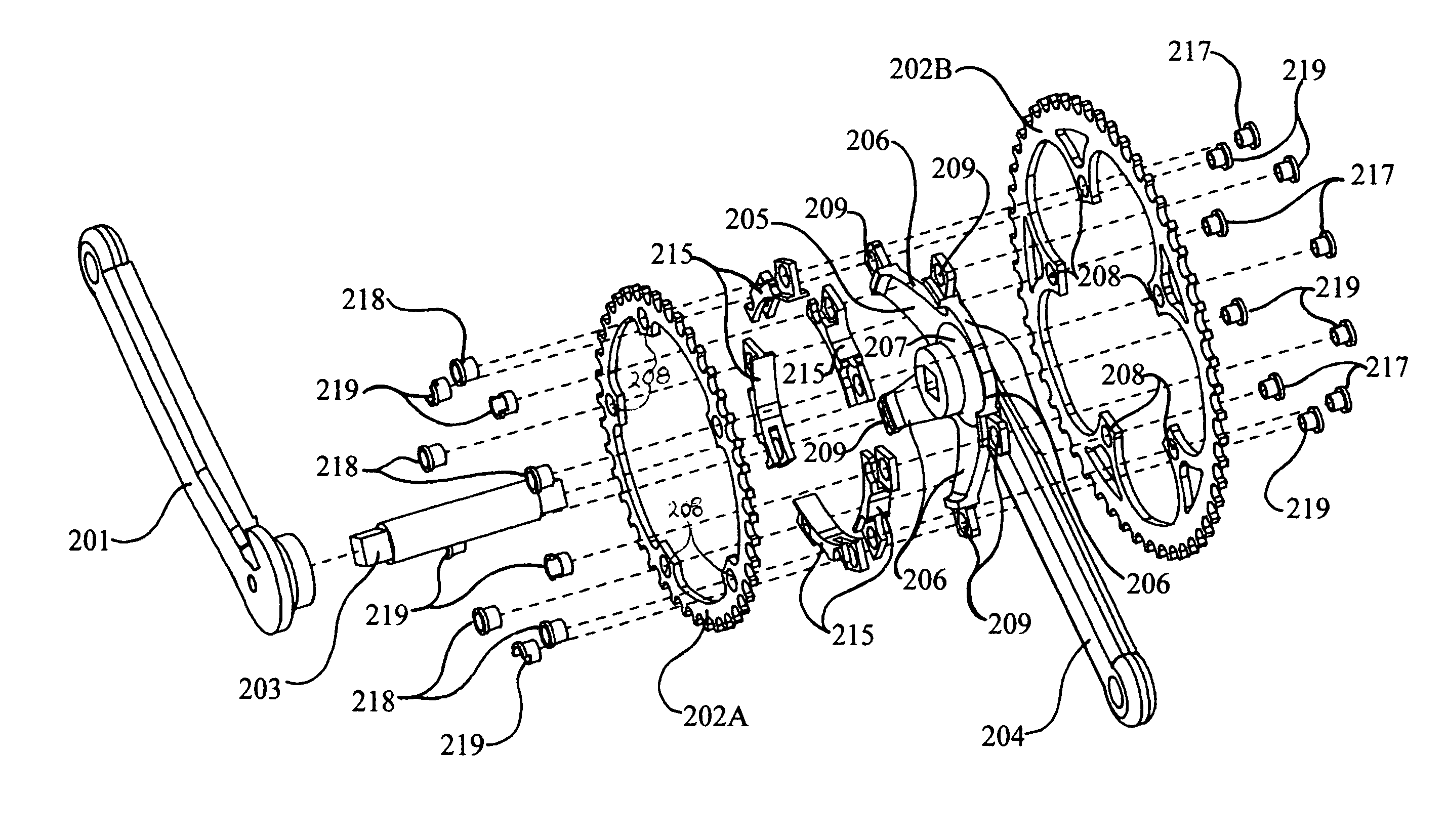
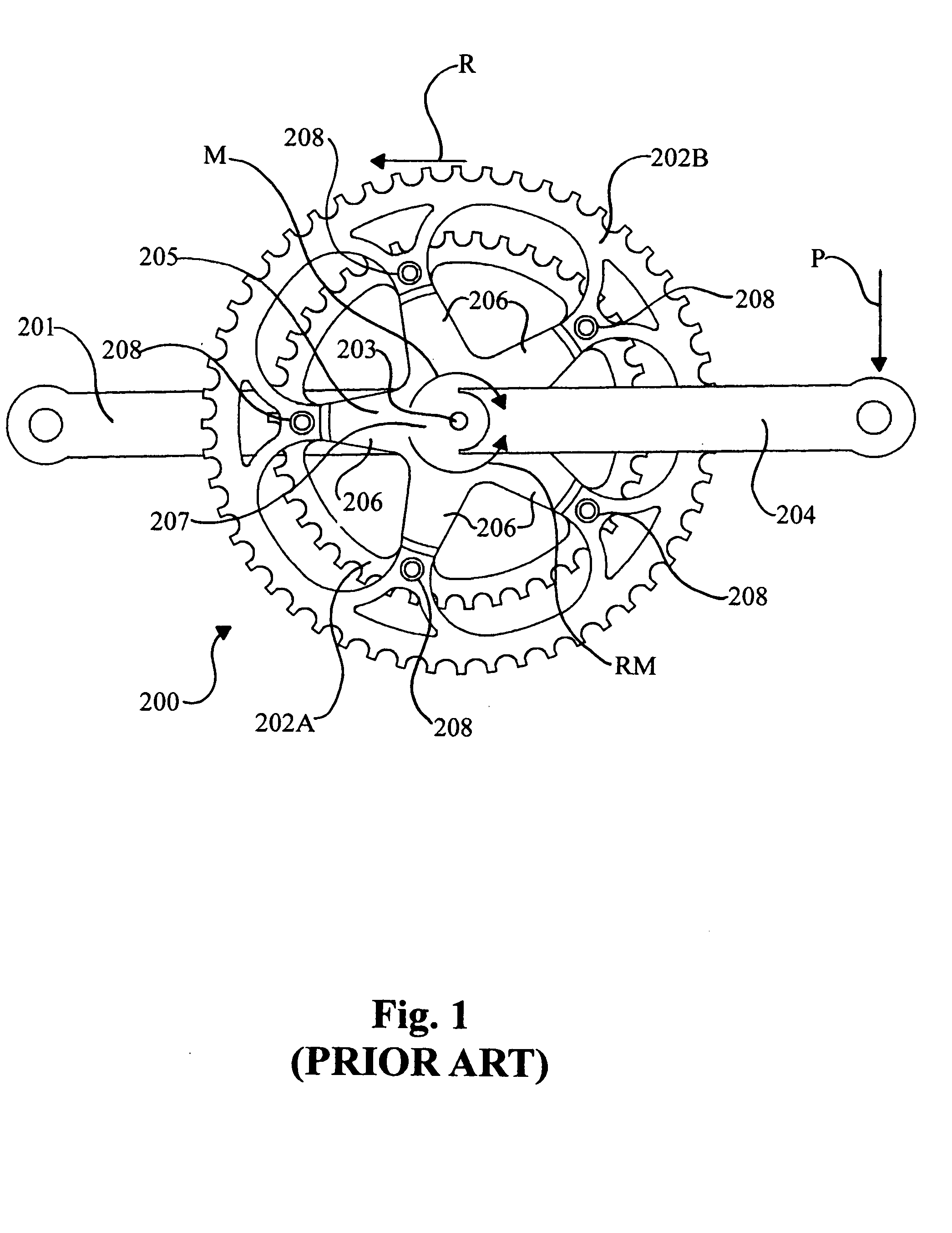
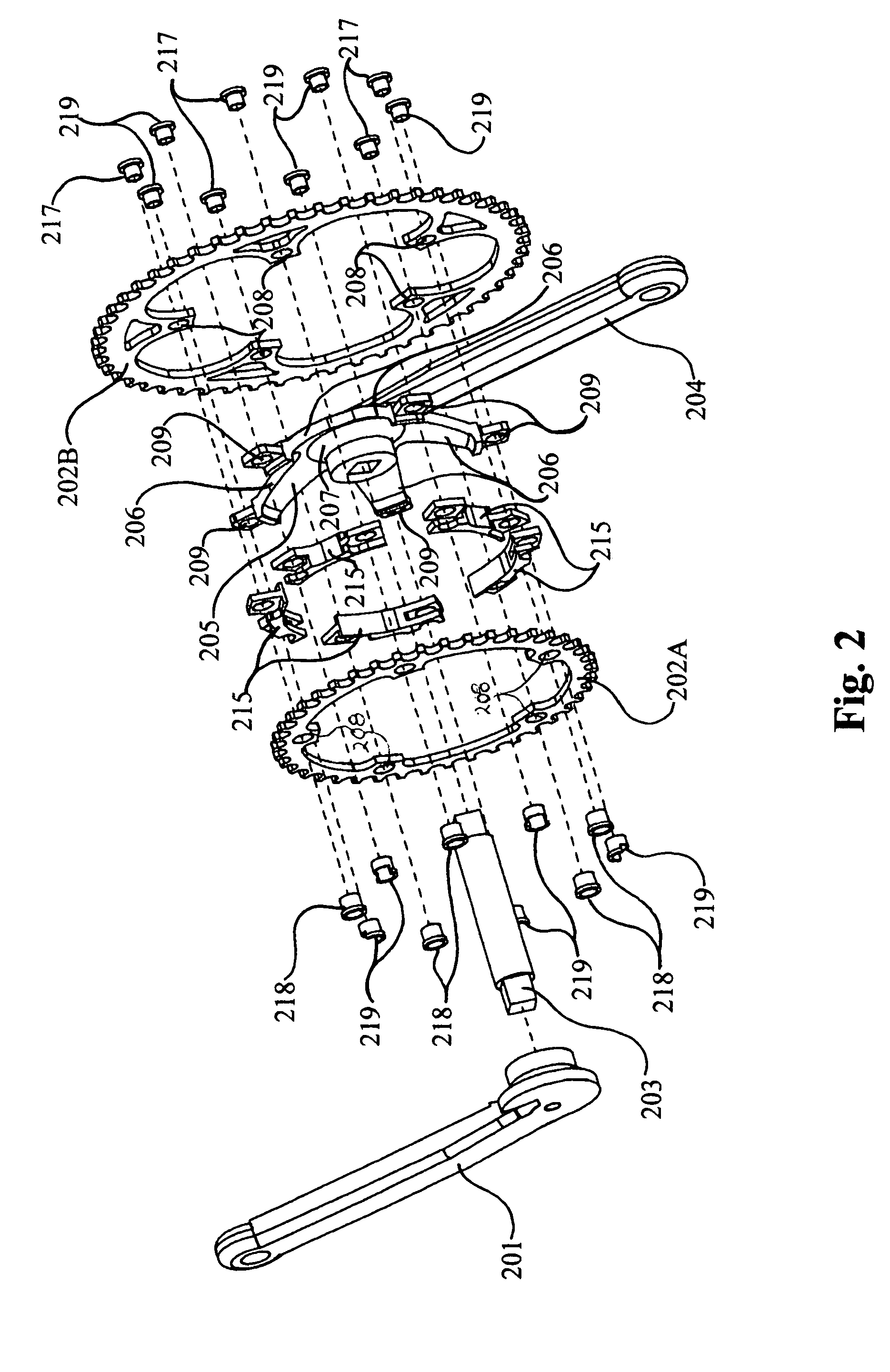
[0038] A conventional cycle chainring and crank assemblage, 200, is shown in FIG. 2. The apparatus and methods of this invention, as described hereinbelow, may be applied with all such conventional assemblages. Crank arm 201 is spaced from chainrings 202A and 202B (a greater or lesser number of chainrings may be provided in any give embodiment used with the apparatus and methods of this invention, as is known), and is attached to the drive train of the cycle by bottom bracket axle 203 (see also FIG. 2). Crank arm 204 is attached to (or integral with) chainring mount 205 (a conventional “spider”, for example, having radiating fingers 206—typically five fingers extending radial out from center 207 of mount 205), mount 205 receiving axle 203. Corresponding structural attachment locales 208 of chainrings 202A and 202B are affixed at attachment sites 209 at the outer extent of mount fingers 206 (see also FIG. 2) using nut and bolt assemblies.

[0039] As shown by the arrows in FIG. 1, the ...


PUM

PropertyMeasurementUnit
compressive strainaaaaaaaaaa
tensile strainaaaaaaaaaa
compressiveaaaaaaaaaa

Abstract

Apparatus and methods for use in measurement of applied load at a chainring assemblage of a pedal powered device are provided. The apparatus includes a link adapted for interposition between a chainring attachment site located on a conventional chainring mount, or spider, and a corresponding chainring attachment locale at a conventional chainring. The link has a geometry and / or material composition selected to accommodate measurement of load exhibited between the attachment site and the corresponding chainring attachment locale. Means for measuring the load exhibited thereby is associated with the link.

Description

FIELD OF THE INVENTION [0001] This invention relates to devices capable of measuring power output while pedaling a pedal powered device such as a bicycle, and, more particularly, relates to such devices located at the chainring assemblage of the device. BACKGROUND OF THE INVENTION [0002] Cycling enthusiasts continue to seek improvement in their performance riding a bicycle. One barrier to such improvement has been ready accessibility to means for measurement of performance both generally and in specific road situations (hilly terrain for example). [0003] One common means used to monitor training performance is the heart rate monitor. While this is a fine training tool, it does have drawbacks, including difficulty, from one ride to the next, in gauging cyclist's riding intensity. It is, therefore, difficult to determine if any progress has been made in training using only a heart rate monitor. [0004] A better way to keep track of a cyclist's performance is to monitor the power genera...

Claims


Application Information

Patent Timeline
Patent Type & Authority Applications(United States)
IPC IPC(8): B62J99/00B62M9/00F16H55/06G01L3/14G01L3/24
CPCB62J99/00B62J2099/0013B62J2099/002G01L3/242B62M9/00G01L3/1457B62K2207/00B62J45/41B62J45/421B62J50/22
Inventor LANHAM, GREGORY T.
Owner FORZA
Learn More