An underground optical cable transfer box for preventing from being submerged in water

An optical cable transfer box and buried technology, which is applied in the field of waterproof protection of optical cable transfer boxes, can solve the problems of signal transmission monitoring equipment damage, buried optical cable transfer boxes are easy to be submerged in water, etc., so as to prolong the service life and prevent artificial Destructive, hard-to-exit effects

Active Publication Date: 2017-01-11
杭州华宏通信设备有限公司
View PDF6 Cites 0 Cited by
  • Summary
  • Abstract
  • Description
  • Claims
  • Application Information

AI Technical Summary

Problems solved by technology

[0004] The present invention aims to solve the problem that when the existing buried optical cable transfer box is used in a pit that is easily flooded by water, if there is a large amount of water in the pit, it will cause the buried optical cable transfer box to be easily flooded by water, resulting in signal transmission. Insufficient monitoring equipment damage, providing a buried optical cable transfer box to prevent being submerged in water, the buried optical cable transfer box can automatically rise according to the rise of the water level in the pit, and according to the drop of the water level in the pit And automatically descend, and automatically reset after the water in the pit disappears and install it on the base

Method used


Image

  • An underground optical cable transfer box for preventing from being submerged in water
  • An underground optical cable transfer box for preventing from being submerged in water
  • An underground optical cable transfer box for preventing from being submerged in water

Examples


Embodiment

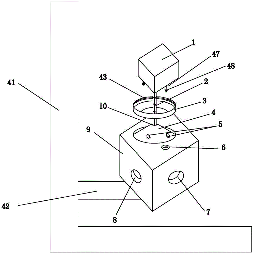
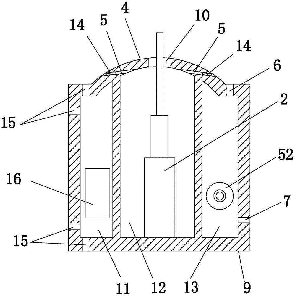
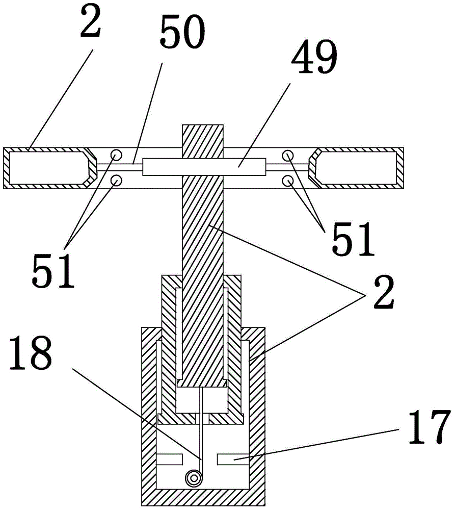
[0037] Embodiment: a kind of buried optical cable splicing box that prevents from being submerged in water, see figure 1 Shown, comprise base 9, annular buoyant tank 3 and the telescopic pull rod 2 that prevents rotation; At the center of the upper surface of the base, be provided with a spherical shape that protrudes upward and matches the inner ring outer wall of the circular buoyant tank. Convex cap 4; Lock pin power cavity 11, pull rod placement cavity 12 and optical cable placement cavity 13 are respectively provided in the base, and a pull rod telescopic hole 10 leading to the pull rod placement cavity is provided on the upper surface of the spherical convex cap. The seat is provided with an inlet hole and an outlet hole 6 communicating with the optical cable placement cavity, and the inlet hole is provided with an inlet hole on each side of the base, see figure 1 The shown wire inlet hole 7 and wire inlet hole 8. The outer surface of the base is provided with several f...


PUM


Abstract

The invention discloses an embedded optical cable splice box prevented from being submersed by water, and belongs to the technical field of optical cable splice box water resistance and protection. The embedded optical cable splice box can ascend or descend automatically according to rising or falling of the water level of water accumulated in a pit till the splice box returns back to the original position. The embedded optical cable splice box comprises a base, a circular buoyancy tank and a telescopic pull rod. An embedded optical cable splice box body is arranged above the circular buoyancy tank, the lower bottom face of the embedded optical cable splice box body is fixed to the top end of the telescopic pull rod, and the bottom end of the telescopic pull rod is fixed to the inner wall of a pull rod placing cavity. An air-pressure lock pin controlled by an air-pressure control device is arranged in a pin hole of the base. The air-pressure control device comprises an air-pressure piston cylinder, a rope and a buoyancy power mechanism. The buoyancy power mechanism pulls and drives a piston of the air-pressure piston cylinder through the rope by virtue of the ascending buoyancy to move so as to drive the air-pressure lock pin to be opened and closed, so that the embedded optical cable splice box can freely ascend and descend under the action of the buoyancy of the circular buoyancy tank, and it is guaranteed that a signal transmission and monitoring device in the embedded optical cable splice box cannot be submersed by flood.

Description

technical field [0001] The invention relates to the technical field of waterproof protection for an optical cable transfer box, in particular to an underground optical cable transfer box that prevents it from being submerged in water. Background technique [0002] Because the buried optical cable transfer box is generally arranged in the pit on the ground beside the urban road. For example, the buried fiber optic cable junction box in the city is generally arranged on the roadside or in the pit on the empty ground of the community. Now in some cities, there will be water in the pits where the buried optical cable transfer box is installed when there is a heavy rain. If the accumulated water in the pit continues to rise, it will submerge the buried optical cable junction box in the pit. Since the buried optical cable transfer box is equipped with high-precision signal transmission monitoring equipment, once the buried optical cable transfer box is submerged in water, it wil...

Claims


Application Information

Patent Timeline
Patent Type & Authority Patents(China)
IPC IPC(8): G02B6/44G02B6/50
Inventor 巩少荧
Owner 杭州华宏通信设备有限公司
Why Eureka
Try Eureka