
Method and system for positioning local CT scanning with assistance of visible imaging

An auxiliary positioning and CT scanning technology, applied in image analysis, image data processing, instruments, etc., can solve the problems of reducing system flexibility and practicability, failing to meet local CT imaging requirements well, and unable to adapt to imaging requirements, etc. Achieve efficient deployment, improve flexibility and practicality

Active Publication Date: 2014-11-12
TSINGHUA UNIV +1
View PDF5 Cites 12 Cited by
  • Summary
  • Abstract
  • Description
  • Claims
  • Application Information

AI Technical Summary

Problems solved by technology

Therefore, in order to ensure the mechanical accuracy of the CT scanning system, installing an industrial CT scanning system generally requires a long period of debugging, which leads to great difficulties in realizing the mechanical layout and control of large-sized objects with special shapes, and the CT scanning system cannot be realized. The purpose of efficient deployment and flexible mobility cannot adapt to the imaging requirements in complex environments, which reduces the flexibility and practicability of the system, and cannot well meet the local CT imaging requirements of the region of interest

Method used


Image

  • Method and system for positioning local CT scanning with assistance of visible imaging
  • Method and system for positioning local CT scanning with assistance of visible imaging
  • Method and system for positioning local CT scanning with assistance of visible imaging

Examples


Embodiment Construction

[0042] The embodiments of the present invention are described in detail below. Examples of the embodiments are shown in the accompanying drawings, in which the same or similar reference numerals indicate the same or similar elements or elements with the same or similar functions. The embodiments described below with reference to the accompanying drawings are exemplary, and are only used to explain the present invention, and cannot be construed as limiting the present invention.

[0043] The following disclosure provides many different embodiments or examples for implementing different structures of the present invention. In order to simplify the disclosure of the present invention, the components and settings of specific examples are described below. Of course, they are only examples, and are not intended to limit the invention. In addition, the present invention may repeat reference numbers and / or letters in different examples. This repetition is for the purpose of simplificat...


PUM


Abstract

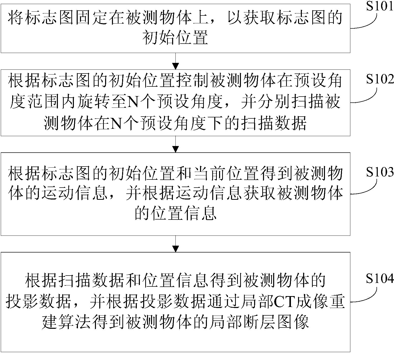
The invention discloses a method and a system for positioning local CT scanning with assistance of visible imaging. The method comprises the following steps: fixing a mark graph on a tested object so as to acquire a primary position of the mark graph; controlling the tested object to rotate for N predetermined angles in a predetermined angle range according to the primary position of the mark graph, and respectively scanning the tested object under N predetermined angles to acquire scanning data; acquiring motion information of the tested object according the primary position and the current position of the mark graph, and acquiring the position information of the tested object according to the motion information; acquiring the projection data of the tested object according to the scanning data and the position information, and acquiring a local tomographic image of the tested object according to the projection data by using a local CT imaging reconstruction algorithm. According to the method, local CT scanning can be realized under the situation that mechanical control accuracy cannot be ensured due to the limit of the complex environmental conditions; the flexibility and the practicability of the system are improved; and the purposes of effective movement and flexible movement of the system can be well achieved.

Description

Technical field [0001] The present invention relates to the technical field of X-ray computer tomography, in particular to a visible light imaging assisted localization CT scanning method and system. Background technique [0002] In related technologies, the realization of CT scanning is based on X-ray sources such as X-ray machines and high-energy accelerators irradiating objects, and linear array (for example, two-dimensional scanning) or area array (for example, three-dimensional scanning) detectors are used to collect data. Among them, the scanning process obtains the light intensity data of the X-ray passing through different positions of the object at different angles through the relative rotation and translation of the object and the light source or the detector, and the tomographic image of the detected object can be reconstructed according to the obtained light intensity data. [0003] However, CT scanning usually requires high-precision control of the trajectory and relat...

Claims


Application Information

Patent Timeline
IPC IPC(8): G01N23/04G06T7/00
Inventor 邢宇翔陈羽加曹萌刘永盛黄伟健王正安张丽陈志强刘宾梁保权肖永顺
Owner TSINGHUA UNIV
Learn More