Heat dissipation device for hydraulic system

A hydraulic system and heat dissipation device technology, which is applied to fluid pressure actuation devices, fluid pressure actuation system components, mechanical equipment, etc., can solve problems such as poor heat dissipation effect, complicated feeling, and increased equipment footprint, so as to improve heat dissipation effect, cost reduction effect

Inactive Publication Date: 2014-11-12
ANHUI UNIV OF SCI & TECH
View PDF6 Cites 2 Cited by
  • Summary
  • Abstract
  • Description
  • Claims
  • Application Information

AI Technical Summary

Problems solved by technology

[0002] When the hydraulic system is working, the temperature of the entire hydraulic system rises due to the throttling and overflow of the system. The hydraulic system is generally placed at ambient temperature or blown by a fan to dissipate heat. If the hydraulic system is placed at ambient temperature to dissipate heat, the heat dissipation effect is poor. If the fan is used to blow and dissipate heat, the area of ​​the hydraulic system will be increased, and the cost will be increased accordingly
The existing cooling device adopts the circulation oil pipe and the hydraulic system to form a rectangular circulation system, but the rectangular circulation system uses a short distance to flow through the water tank radiator of the water-cooled engine, so the heat dissipation effect is not good. In order to improve the heat dissipation effect, increase The height of the hydraulic system, although such an improvement has improved the heat dissipation of the hydraulic system to a certain extent, it has increased the space occupied by the equipment, and the overall feeling is more complicated

Method used


Image

  • Heat dissipation device for hydraulic system

Examples


Embodiment Construction

[0012] In order to make the objects and advantages of the present invention clearer, the present invention will be further described in detail below in conjunction with the examples. It should be understood that the specific embodiments described here are only used to explain the present invention, not to limit the present invention.

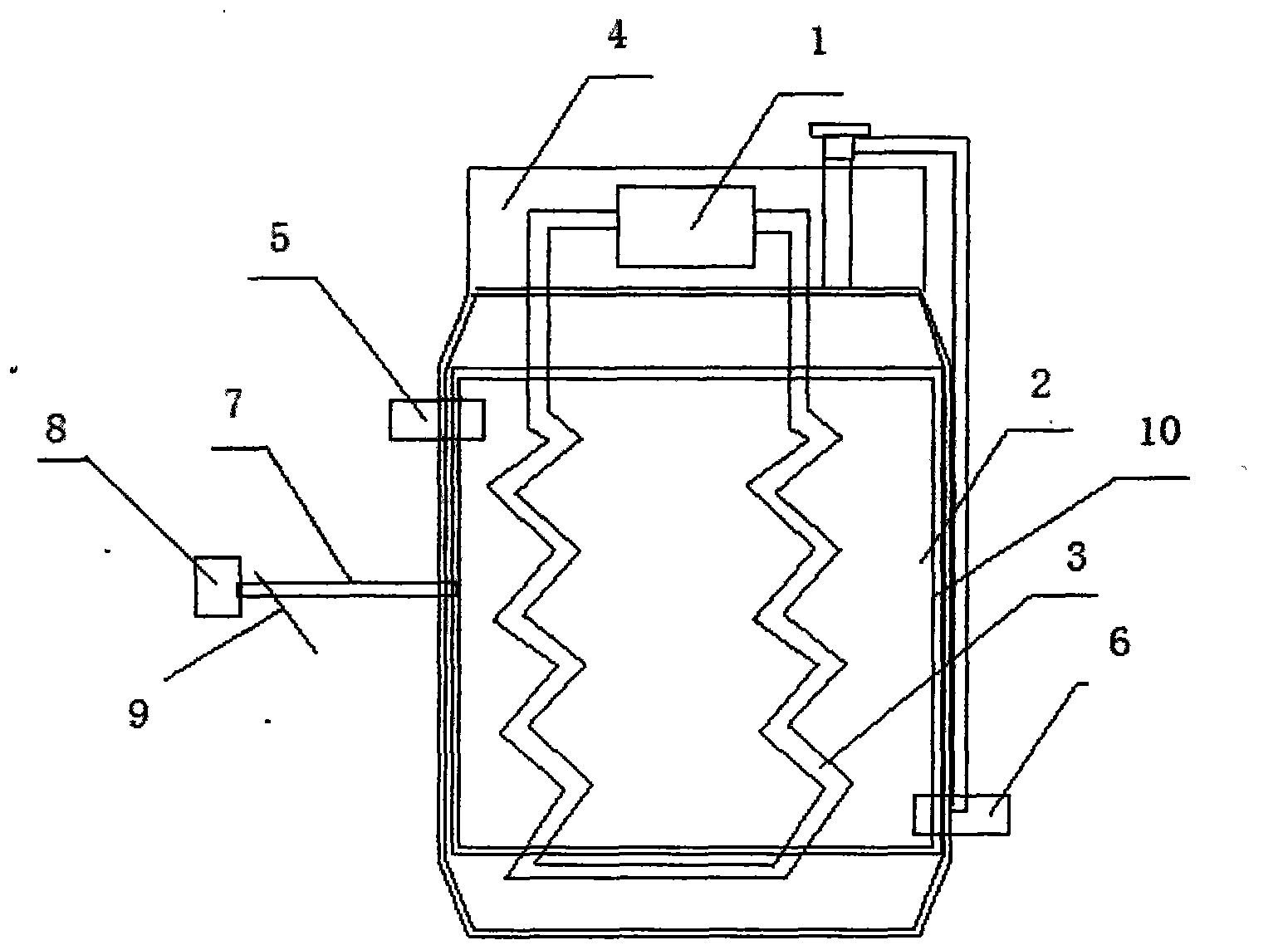
[0013] Such as figure 1 As shown, the embodiment of the present invention provides a heat dissipation device for a hydraulic system, including a water-cooled engine radiator 2 and a hydraulic system 1. The hydraulic system 1 is externally connected to a circulating oil pipe 3, and the circulating oil pipe 3 is placed in a water-cooled engine radiator. 2, a cavity 4 is provided above the radiator 2 of the water-cooled engine, the hydraulic system 1 and the ends of the circulating oil pipe 3 connecting the two ends of the hydraulic system 1 are located in the cavity 4, and the circulating oil pipe 3 Placed in a water-cooled engine radiator 2 in a...


PUM


Abstract

The invention discloses a heat dissipation device for a hydraulic system. The heat dissipation device comprises a water-cooled engine water tank heat dissipation device and the hydraulic system, wherein the hydraulic system is externally connected with a circulating oil pipe, the circulating oil pipe is arranged in the water-cooled engine water tank heat dissipation device, a cavity is arranged above the water-cooled engine water tank heat dissipation device, the hydraulic system and end parts, which are connected with two ends of the hydraulic system, of the circulating oil pipe are both located in the cavity, and the circulating oil pipe is arranged in the water-cooled engine water tank heat dissipation device and is of a helical structure. According to the heat dissipation device for the hydraulic system, disclosed by the invention, the circulating oil pipe is set to be a helical shape, thus the time that the circulating oil pipe passes through the water-cooled engine water tank heat dissipation device is increased, the heat dissipation effect of the hydraulic system is greatly increased, the cavity is arranged above the water-cooled engine water tank heat dissipation device and is used for placing the hydraulic system, the whole heat dissipation device is simpler, the area of the hydraulic system does not need to be increased, the cost is correspondingly reduced, meanwhile, the temperature of the water-cooled engine water tank heat dissipation device can be instantaneously reduced by the design of a refrigeration layer, and the heat dissipation effect is further increased.

Description

technical field [0001] The invention relates to a heat dissipation device, in particular to a heat dissipation device for a hydraulic system. Background technique [0002] When the hydraulic system is working, the temperature of the entire hydraulic system rises due to the throttling and overflow of the system. The hydraulic system is generally placed at ambient temperature or blown by a fan to dissipate heat. If the hydraulic system is placed at ambient temperature to dissipate heat, the heat dissipation effect is poor. If a fan is used to blow air and dissipate heat, the area of ​​the hydraulic system will be increased, and the cost will be increased accordingly. The existing cooling device adopts the circulation oil pipe and the hydraulic system to form a rectangular circulation system, but the rectangular circulation system uses a short distance to flow through the water tank radiator of the water-cooled engine, so the heat dissipation effect is not good. In order to imp...

Claims


Application Information

Patent Timeline
IPC IPC(8): F15B21/04
Inventor 张辉张义龙黄坤刁梁汪秒陈世豪潘跃芸潘兆轩储诚兵王进鹏黄少飞
Owner ANHUI UNIV OF SCI & TECH
Why Eureka
Try Eureka