
Oscillating type dampers used for vibration prevention of tower

A damper and swing-type technology is applied in the development and design field of swing dampers for tower anti-vibration, which can solve the problems of few studies on wind-proof and vibration-proof shock absorbers.

Active Publication Date: 2014-11-12
TIANJIN UNIV
View PDF5 Cites 6 Cited by
  • Summary
  • Abstract
  • Description
  • Claims
  • Application Information

AI Technical Summary

Problems solved by technology

[0005] At present, the commonly used anti-vibration methods for towers at home and abroad are mainly to add spoilers such as fins and baffles, and there are still few studies on anti-wind vibration dampers.

Method used


Image

  • Oscillating type dampers used for vibration prevention of tower
  • Oscillating type dampers used for vibration prevention of tower
  • Oscillating type dampers used for vibration prevention of tower

Examples


example 1

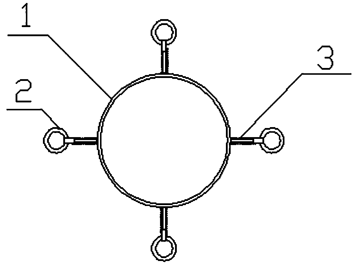
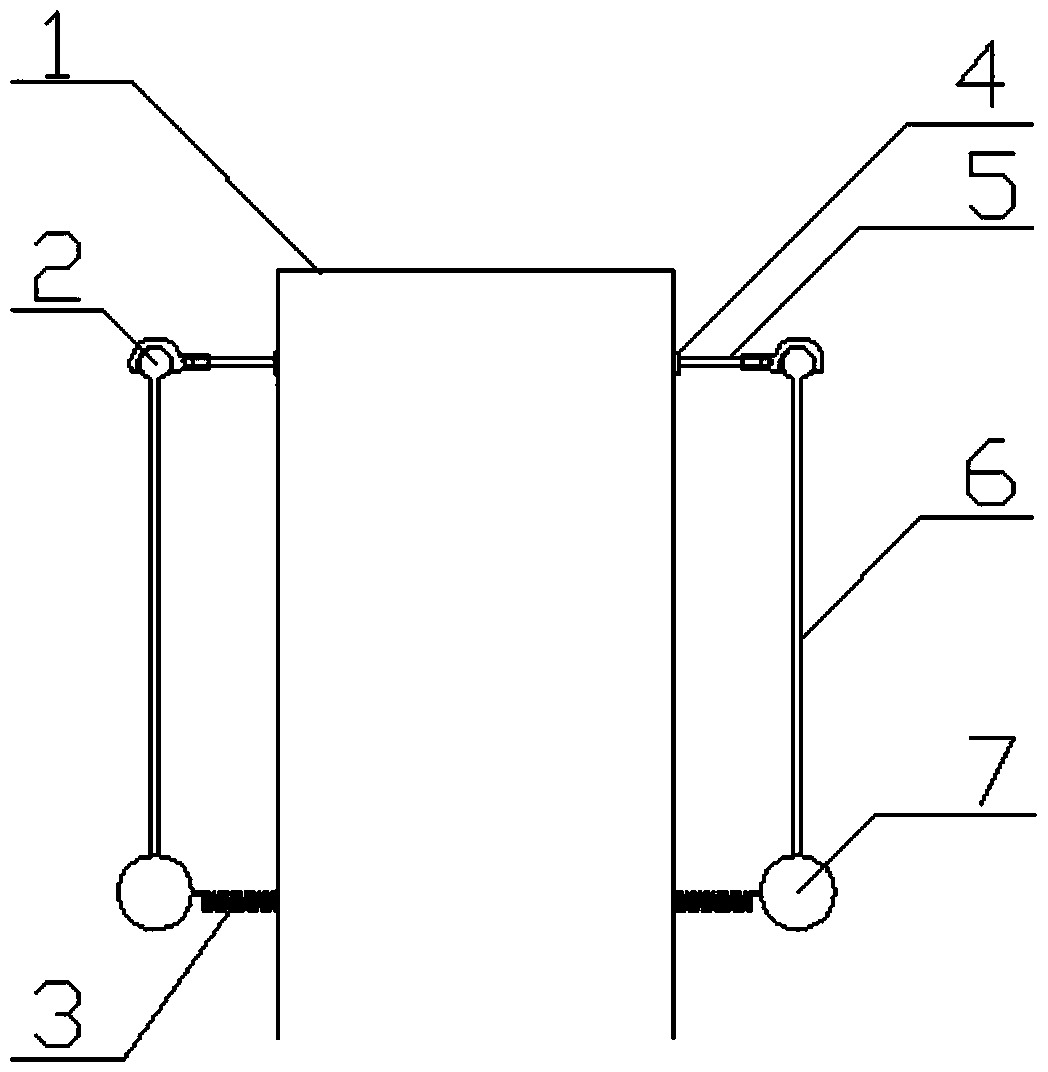
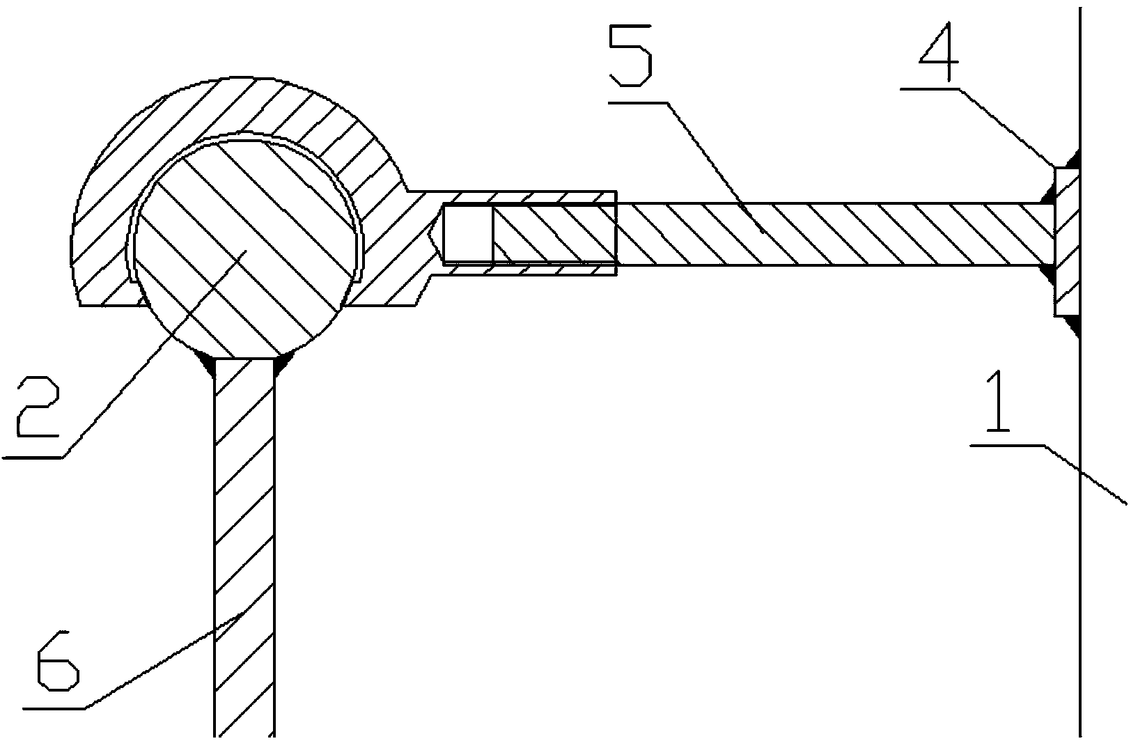
[0055] will figure 2 The damper shown is installed on the top of the tower. One end of the connecting rod 5 is welded to the tower body 1, and the other end is threaded to the ball hinge 2; the pendulum rod 6 is perpendicular to the connecting rod 5, one end of the pendulum rod 6 is welded to the ball hinge 2, and the other end is welded to the mass 7; the spring 3 is connected to the connecting rod. The rod 5 is parallel, one end is welded to the mass 7 and the other end is welded to the tower body 1; there are four dampers in a symmetrical arrangement. Set the connecting rod length to be equal to the tower radius, and set the mass ratio μ to 2%. Under the above conditions, the length ratios of the pendulum rods are set to be 5%, 6.6%, 7.3%, 8%, and 9% respectively. By setting the spring stiffness system k, the vibration frequency of the mass block is consistent with the first-order natural frequency f of the tower. It is proved by experiments that the amplitude y of the to...

example 2

[0057] will figure 2 The damper shown is installed on the top of the tower. One end of the connecting rod 5 is welded to the tower body 1, and the other end is threaded to the ball hinge 2; the pendulum rod 6 is perpendicular to the connecting rod 5, one end of the pendulum rod 6 is welded to the ball hinge 2, and the other end is welded to the mass 7; the spring 3 is connected to the connecting rod. The rod 5 is parallel, one end is welded to the mass 7 and the other end is welded to the tower body 1; there are four dampers in a symmetrical arrangement. Set the connecting rod length equal to the tower radius, and set the pendulum rod length ratio to 9%. Under the above conditions, the mass ratio μ is set to 0.65%, 1.3%, 2%, 3.3%, and 4%, respectively. By setting the spring stiffness system k, the vibration frequency of the mass block is consistent with the first-order natural frequency f of the tower. It is proved by experiments that the amplitude y of the tower top T1 Decr...


PUM


Abstract

The invention relates to oscillating type dampers used for vibration prevention of a tower. Each oscillating type damper is composed of a connection rod, a spherical hinge, an oscillating bar, a mass block and a spring, wherein one end of the connection rod is connected with a tower body, and the other end of the connection rod is in threaded connection with the spherical hinge; the oscillating bar is perpendicular to the connection rod, one end of the oscillating bar is connected with the spherical hinge in a welded mode, and the mass block is welded to the other end of the oscillating bar; the spring is parallel to the connection rod, one end of the spring and the mass block are connected in a welded mode, and the other end of the spring and the tower body are connected in a welded mode. The dampers are arranged symmetrically. Vibration prevention measures are taken when resonance of the tower occurs. The amplitude of vibration of the tower body is reduced rapidly by increasing damping of the tower body, the resonance amplitude of a tower top is reduced, and accordingly damage to the tower from resonance is reduced.

Description

Technical field [0001] The invention relates to a damper for tower vibration prevention, in particular to the development and design of a swing damper for tower vibration prevention under wind-induced vibration. Background technique [0002] The tower is one of the most important equipment in chemical production. As a special equipment, once an accident occurs, it will be extremely harmful. Therefore, it is very necessary to ensure the safe operation of the tower. [0003] The aspect ratio of the tower is relatively large. Therefore, during operation, the tower body not only bears loads such as gravity and operating pressure, but also is greatly affected by wind loads. The tower installed outdoors will vibrate in two directions under the action of wind load. One is downwind vibration, that is, the vibration direction of the tower is parallel to the wind direction; the other is crosswind vibration, that is, the vibration direction is perpendicular to the wind direction, which is ...

Claims


Application Information

Patent Timeline
IPC IPC(8): E04B1/98
Inventor 谭蔚徐乐田雅婧
Owner TIANJIN UNIV
Learn More