A leak-proof device for the gluing mechanism of an edge banding machine

A technology of anti-leakage device and edge banding machine, which is applied to devices and coatings that apply liquid to the surface, can solve the problems of poor sealing of the gluing mechanism, leakage of glue, and short bearing life, so as to reduce the storage amount of glue. , Reduce the possibility of glue leakage, good leakage prevention effect

Active Publication Date: 2016-06-08
NANXING MACHINERY CO LTD
View PDF5 Cites 0 Cited by
  • Summary
  • Abstract
  • Description
  • Claims
  • Application Information

AI Technical Summary

Problems solved by technology

Since the gluing shaft has been doing relative rotary motion in a high-temperature environment, it is easy to cause poor sealing of the gluing mechanism. Therefore, on the one hand, it is easy to cause glue to flow into the bearing, and cause the bearing to lock after the glue cools and solidifies, resulting in the gluing mechanism It cannot work normally, on the other hand, it is very easy for glue to leak onto the workbench, which seriously affects the cleanliness of the workbench and the working environment, and is also a waste of glue
[0003] In the prior art, the slender gap between the rotating shaft and the glue supply box and the graphite bearing are generally used for sealing, but this sealing effect is not good, and the glue easily enters the inside of the bearing, and the glue entering the inside of the bearing is prone to bearing lockup Defective phenomenon, resulting in shorter life of the bearing, usually need to replace the bearing during maintenance, resulting in higher maintenance and use costs

Method used


Image

  • A leak-proof device for the gluing mechanism of an edge banding machine
  • A leak-proof device for the gluing mechanism of an edge banding machine
  • A leak-proof device for the gluing mechanism of an edge banding machine

Examples


Embodiment Construction

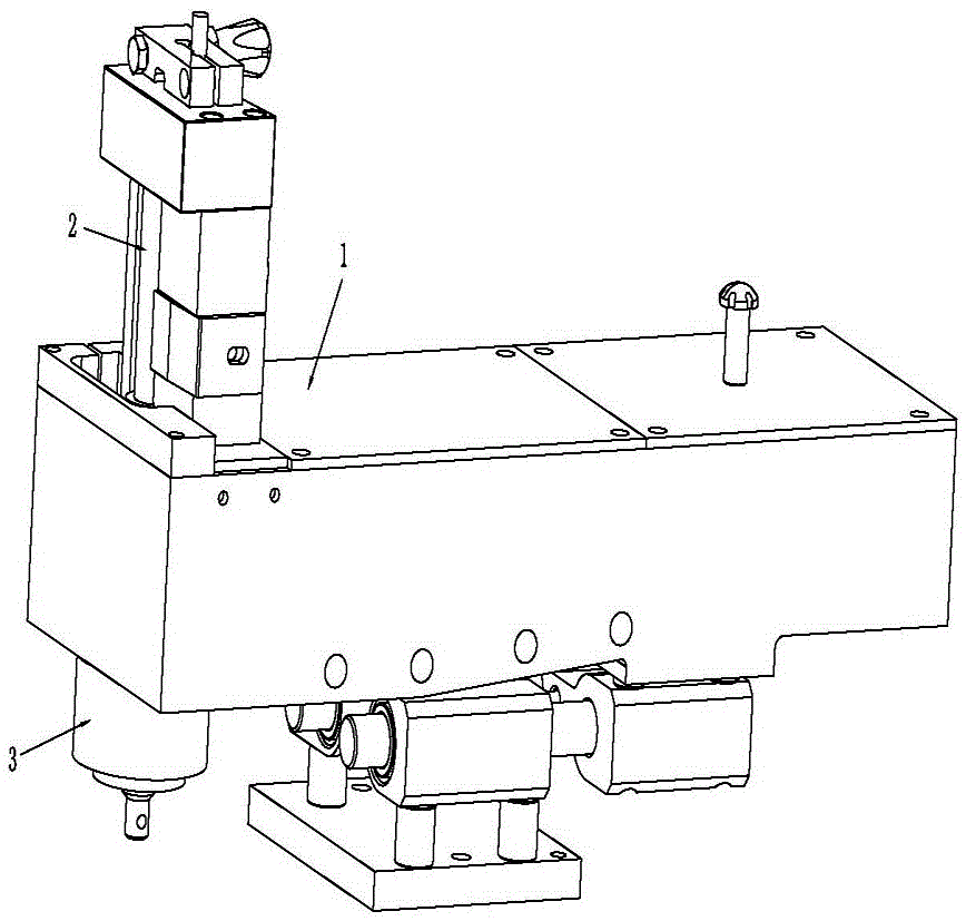
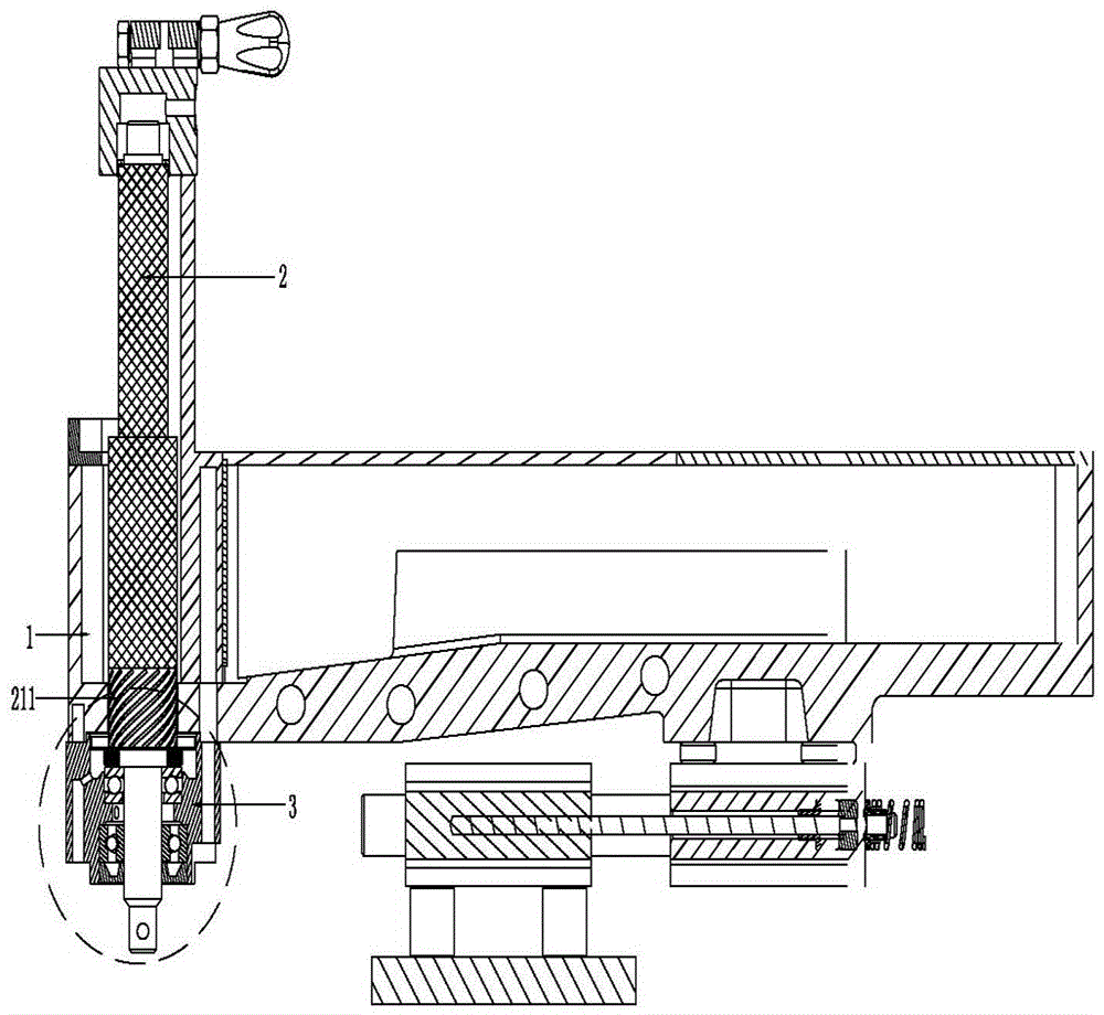
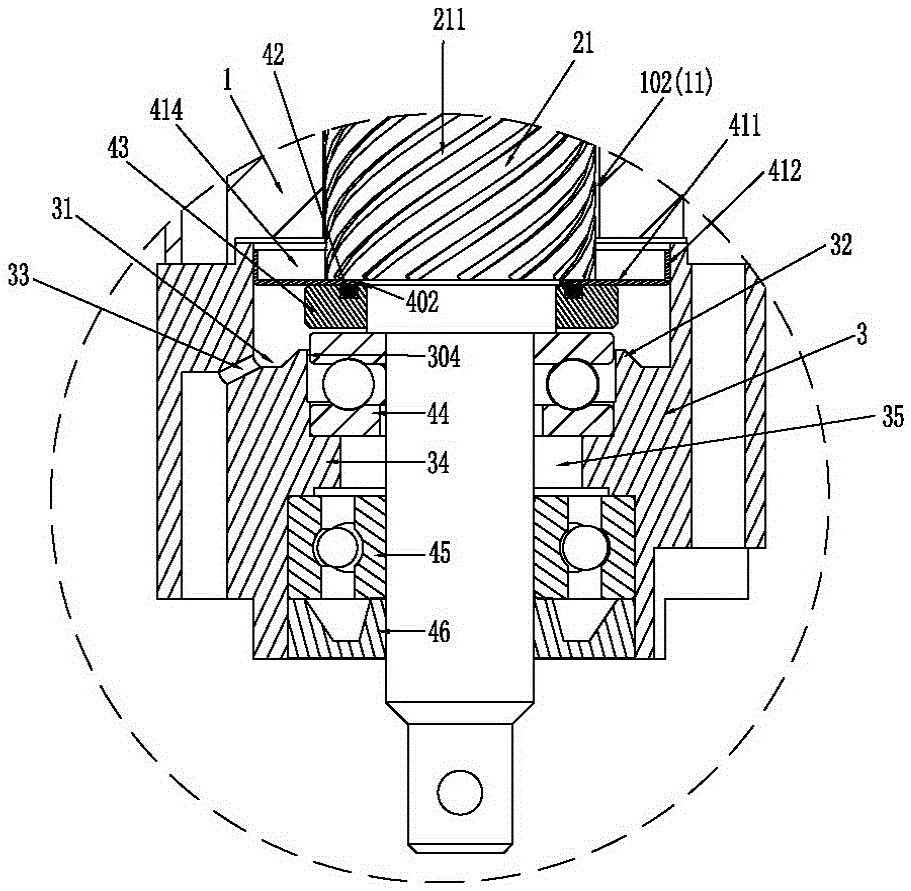
[0047] Please refer to Figure 1 to Figure 5Shown in (b), it has shown the concrete structure of preferred embodiment of the present invention, and it comprises parts such as glue supply box 1, glue-applying shaft 2 and rubber-feeding wheel seat 3, wherein, this glue-applying shaft 2 comprises The gluing shaft working part 21 and the gluing shaft connecting part 22 fixedly connected to each other; the gluing shaft connecting part 22 is rotatably connected in the rubber supply wheel seat 3, and the bottom end of the gluing shaft connecting part 22 passes through The rubber wheel seat 3 extends out of the bottom end of the rubber wheel seat 3, and the glue shaft connection part 22 is responsible for sealing and power transmission; the bottom of the aforementioned glue supply box 1 is provided with a bottom hole 11 for the glue shaft 2 to pass through. The gluing shaft working part 21 vertically penetrates the glue supply box 1 through the bottom hole 11 and protrudes from the to...


PUM


Abstract

The invention discloses an anti-leakage device for a glue application mechanism of an edge banding machine, comprising a glue supply box, a glue application shaft, a rubber supply wheel seat, a sealing cover installed between the rubber supply wheel seat and the glue application shaft, and an O-shaped sealing ring , Bearing; Wherein, the gluing shaft includes the gluing shaft working part and the gluing shaft connecting part fixedly connected to each other; the outer wall surface of the gluing shaft working part is provided with a helical lift whose helical direction is opposite to the gluing shaft rotation direction. Groove, the aforementioned sealing cover is used to accept the leaked glue; during the rotation of the glue shaft, the glue is actively lifted up from the receiving groove and the slender gap to the glue supply box by rotating the lifting groove; effectively avoiding the glue from entering In the case of locking inside the bearing, even if the sealing element is slightly worn, the normal operation of the equipment can still be guaranteed, and only the O-ring is replaced during maintenance, and there is no need to replace the high-temperature bearing. The maintenance cost is lower and effective. It solves the problems of bearing locking and maintenance troubles that often occur in traditional gluing devices.

Description

technical field [0001] The invention relates to the technology in the field of woodworking machinery, in particular to an anti-leakage device for the gluing mechanism of an edge banding machine which prevents the gluing shaft from locking and has a good leak-proof effect. Background technique [0002] At present, when the gluing device of the edge banding machine in the domestic and foreign markets is working, the high-temperature glue in the glue supply box is driven by the rotation of the gluing shaft to lift, so that the glue is evenly covered on the surface of the working part of the gluing shaft to achieve gluing. Function. Since the gluing shaft has been doing relative rotary motion in a high-temperature environment, it is easy to cause poor sealing of the gluing mechanism. Therefore, on the one hand, it is easy to cause glue to flow into the bearing, and cause the bearing to lock after the glue cools and solidifies, resulting in the gluing mechanism Can not work norm...

Claims


Application Information

Patent Timeline
Patent Type & Authority Patents(China)
IPC IPC(8): B05C11/00B05C11/10
Inventor 王同乐容世桢孟岩
Owner NANXING MACHINERY CO LTD
Why Eureka
Try Eureka