Rotary piston

A rotary piston, rotary piston pump technology, applied in rotary piston pumps, rotary piston machines, pistons, etc., can solve the problems of wear and tear of elastomer material strips, failure of rotary piston pumps, etc., and achieve the effect of preventing clogging

Inactive Publication Date: 2014-11-05
NETZSCH PUMPEN & SYST +1
View PDF10 Cites 1 Cited by
  • Summary
  • Abstract
  • Description
  • Claims
  • Application Information

AI Technical Summary

Problems solved by technology

This prior art shows that strips of elastomeric material are subject to severe wear
Furthermore, when there are high loads, this can have a counterproductive effect in operation if the sealing strip actually runs the risk of detaching from the support body due to breakage at the breaking point
This can cause the rotary lobe pump to fail completely or be severely damaged

Method used


Image

  • Rotary piston
  • Rotary piston
  • Rotary piston

Examples


Embodiment Construction

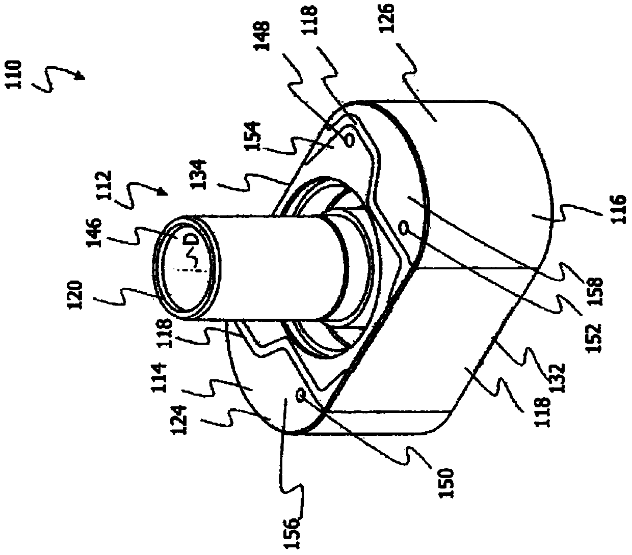
[0039] figure 1 A perspective view of a rotary piston 10 according to a first embodiment of the invention is shown. Such a rotary piston 10 can be used, for example, in a rotary piston pump as described in document DE 10 2010 014 248 A1.

[0040] The rotary piston 10 comprises a support body 12 and an end cover part 14 and 16 each radially outside the support body. The support body 12 is connected to the end caps 14 , 16 by an elastomeric cushioning layer 18 . Elastomeric cushioning layer 18 such as figure 1 As shown, it is formed around the support body 12 .

[0041] The support body 12 also comprises an opening 20 forming the hub of the rotary piston 10, which opening accommodates a shaft (not shown) for driving the rotary piston 10 when the rotary piston 10 is in the installed state in the rotary piston pump. In order to enable the connection to the shaft (not shown) of the rotary lobe pump, the opening or hub 20 comprises a recess 22 in which a driver part or a matin...


PUM


Abstract

The present invention relates to a rotary piston 10 for a rotary piston pump, wherein the rotary piston 10 comprises at least one supporting body 12, through which the axis of rotation D of the rotary piston 10 extends, and at least one end cap portion 14, 16 which is arranged radially outwards of the at least one supporting body 12 and is connected flexibly, preferably elastically, to the at least one supporting body 12.

Description

technical field [0001] The invention relates to a rotary piston for a rotary piston pump. Background technique [0002] Rotary piston pumps are known from the prior art and, for example, from document DE 102 010 014 248 A1. The rotary piston pump according to this document comprises a motor and a pump housing in which a rotary piston is placed. Furthermore, an inflow opening and an outflow opening are provided in the pump housing. Two rotary pistons placed in the pump housing rotate in opposite directions so that the conveyed medium can be pumped out while there is constant mutual contact. [0003] If a medium containing solids is conveyed by a rotary lobe pump, the rotary piston in the pump housing may be subject to a higher degree of wear, which can cause the rotary piston to fail. The transfer of such media is therefore often accompanied by extensive maintenance work. [0004] Document DE 37 07 722 A1 describes a rotary lobe pump which is also suitable for transferrin...

Claims


Application Information

Patent Timeline
Patent Type & Authority Applications(China)
IPC IPC(8): F01C21/08F04C2/12F04C13/00
CPCF04C2/126F04C2/123F04C13/001F01C21/08F02F3/28
Inventor L·罗兰W·宁德尔B·穆任霍夫R·克兹R·但可J·史达士T·伯梅H·卡莫尔S·魏格尔R·威利斯S·科恩J·克赖德尔G·赫尔M·维尔霍文F·科奈德M·特克纳彦M·格拉德尔E·韦伯
Owner NETZSCH PUMPEN & SYST
Why Eureka
Try Eureka