Controls for hybrid vehicles
A hybrid vehicle and control device technology, applied in hybrid vehicles, power units, pneumatic power units, etc., can solve the problems of poor fuel utilization, increased engine starting vibration, insufficient driving torque, etc. Improve the utilization rate, take into account the fuel utilization rate, suppress or avoid the effect of engine starting vibration
- Summary
- Abstract
- Description
- Claims
- Application Information
AI Technical Summary
Problems solved by technology
Method used
Image
Examples
Embodiment 1
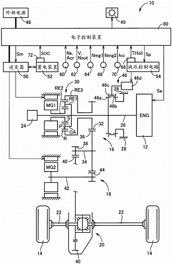
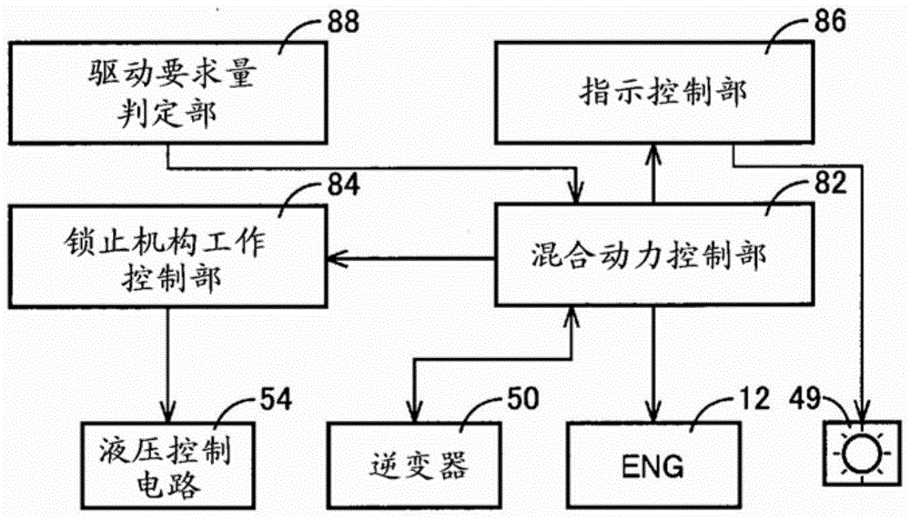
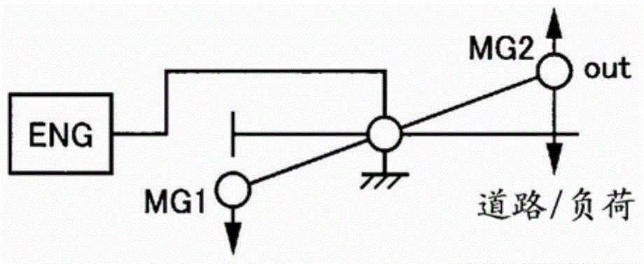
[0036] figure 1 It is a diagram illustrating a schematic configuration of a hybrid vehicle 10 (hereinafter referred to as vehicle 10 ) to which the present invention is applied, and is a block diagram illustrating main parts of a control system provided to control various parts of vehicle 10 . exist figure 1 Among them, the vehicle 10 is configured to include an engine 12 as a driving force source for traveling, a first electric motor MG1, and a second electric motor; A drive unit 18, a differential gear unit 20, a pair of left and right axle shafts 22, and the like. In addition, the vehicle 10 is provided with an oil pump 24 that is driven and rotated by the engine 12 to generate hydraulic pressure as the primary pressure of the hydraulic control circuit 54 and supply lubricating oil to the first drive unit 16 , the second drive unit 18 , and the like. Further, the vehicle 10 includes a dog clutch (dog clutch) 46 as a lockup mechanism for fixing the crankshaft 26 of the eng...
Embodiment 2
[0075] Figure 9 It is a diagram illustrating a schematic configuration of another hybrid vehicle 100 (hereinafter referred to as vehicle 100 ) to which the present invention is applied. as it should Figure 9 As shown, vehicle 100 includes planetary gear unit 102 as a differential mechanism similarly to vehicle 10 , but the connection relationship of engine 12 , first electric motor MG1 , and second electric motor MG2 with respect to planetary gear unit 102 is different from vehicle 10 . In particular, the engine 12 is indirectly connected to the first electric motor MG1 via a clutch C1, and is also connected to the same rotating element (ring gear R) of the planetary gear device 102 . A rotating element (carrier CA) of the planetary gear device 102 to which neither of the plurality of electric motors MG1 and MG2 is connected is connected to the output gear 32 as an output rotating member. The clutch C1 functions as a disconnect clutch that disconnects or connects a power t...
Embodiment 3
[0081] Figure 13 It is a diagram illustrating a schematic configuration of another hybrid vehicle 200 (hereinafter referred to as vehicle 200 ) to which the present invention is applied. as it should Figure 13 As shown, vehicle 200 includes a disconnect clutch K0 that disconnects or connects a power transmission line between engine 12 and electric motor MG, and an automatic transmission 202 that constitutes a part of the power transmission line between electric motor MG and drive wheels 14 . In the vehicle 200, such as Figure 14 As shown in the collinear diagram of , motor travel (motor travel mode) in which only the electric motor MG is used as a driving force source for travel can be realized in a state in which the disconnect clutch K0 is released. In addition, engine running (engine running mode) in which at least the engine 12 is used as a driving force source for running in a state in which the disconnect clutch K0 is engaged can be realized.
[0082] Here, a case ...
PUM
 Abstract
Description
Claims
Application Information
 - R&D Engineer
- R&D Manager
- IP Professional
- Industry Leading Data Capabilities
- Powerful AI technology
- Patent DNA Extraction
Browse by: Latest US Patents, China's latest patents, Technical Efficacy Thesaurus, Application Domain, Technology Topic, Popular Technical Reports.
© 2024 PatSnap. All rights reserved.Legal|Privacy policy|Modern Slavery Act Transparency Statement|Sitemap|About US| Contact US: help@patsnap.com


