Oil pumping unit motor dynamic load simulated loading system and oil pumping unit motor dynamic load simulated loading method

A dynamic load, electromechanical technology, used in motor generator testing and other directions, to achieve strong versatility and save construction costs

Active Publication Date: 2014-11-05
NORTH CHINA ELECTRIC POWER UNIV (BAODING)
View PDF5 Cites 17 Cited by
  • Summary
  • Abstract
  • Description
  • Claims
  • Application Information

AI Technical Summary

Problems solved by technology

[0010] The object of the present invention is to provide a dynamic load simulation loading system and a simulation loading method for pumping unit motors, which are used to solve the problems existing in the existing dynamic load simulation loading systems and loading methods for electric motors

Method used


Image

  • Oil pumping unit motor dynamic load simulated loading system and oil pumping unit motor dynamic load simulated loading method
  • Oil pumping unit motor dynamic load simulated loading system and oil pumping unit motor dynamic load simulated loading method
  • Oil pumping unit motor dynamic load simulated loading system and oil pumping unit motor dynamic load simulated loading method

Examples


example 1

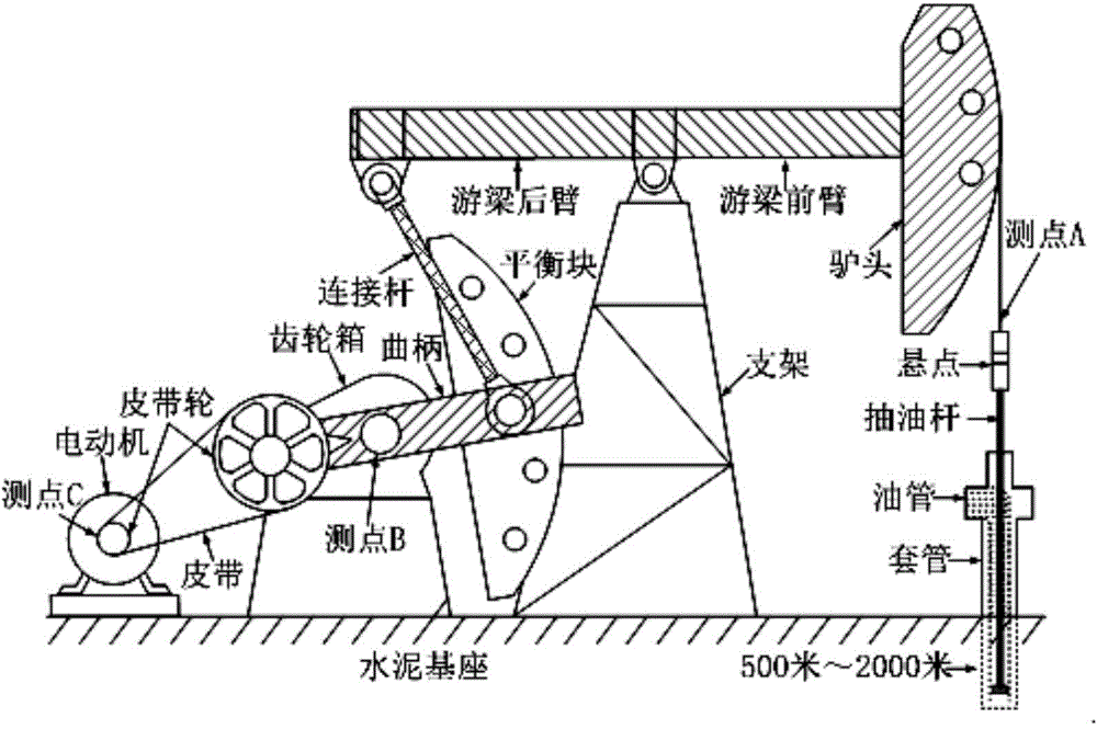
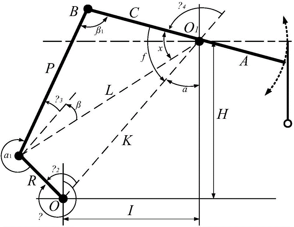
[0124] Pumping unit model: CYJ10-3-37HB; structural parameters: crank R = 1.15m, connecting rod P = 3.35m, beam rear arm C = 2.4m, beam forearm A = 3.0m, base rod projection I = 2.3m, the height of the supporting point of the beam from the center of the gear box is H=3.28m, the structural unbalance block Bw=0; downhole parameters: pump depth L=940m, dynamic fluid surface hoil=300m, sucker rod diameter D=30mm; belt , Gear box parameters: k = 149.33, η = 0.88; four connecting rods: η 1 = 0.95; the load unit selects Siemens S120 series four-quadrant frequency converter and 1FT6 series permanent magnet servo motor, and the driving accuracy is 1.0%. According to the above pumping well parameters, the parameters of the BPs model of the upper computer are correspondingly modified. The tested motor is a Y2 series 8-pole 37kW ordinary three-phase asynchronous motor. The indoor simulation test data and the outdoor pumping unit measured results are as follows: Figure 5 shown. combine ...

example 2

[0126] When the dynamic liquid level is about 400 meters, the test results using the indoor simulation loading system are compared with the measured input power, motor output torque and speed of the outdoor standard well. Figure 7 As shown, among them, Figure 7 (a) is a comparison chart of the input power of the simulated loading system and the actual measurement; Figure 7 (b) is a comparison diagram of the torque of the simulated loading system and the actual measurement; Figure 7 (c) is a comparison chart of the rotational speed of the simulated loading system and the actual measurement. It can be seen that the input active power, load torque and motor speed changes of the tested motor are basically consistent with the measured results of the standard well.

example 3

[0128] When the dynamic liquid level is about 500 meters, the test results using the indoor simulation loading system are compared with the measured input power, motor output torque and speed of the outdoor standard well. Figure 8 As shown, among them, Figure 8 (a) is a comparison chart of the input power of the simulated loading system and the actual measurement; Figure 8 (b) is a comparison diagram of the torque of the simulated loading system and the actual measurement; Figure 8 (c) is a comparison chart of the rotational speed of the simulated loading system and the actual measurement. It can be seen that the input active power, load torque and motor speed changes of the tested motor are basically consistent with the measured results of the standard well.

[0129] The beneficial effects of the present invention are:

[0130] (1) By using the simulated loading system provided in the present invention, when testing the operating performance of the motor under dynamic ...


PUM


Abstract

The invention discloses an oil pumping unit motor dynamic load simulated loading system and an oil pumping unit motor dynamic load simulated loading method in the technical field of motor dynamic load simulated test. The system comprises a torque meter, a belt pulley and gearbox module, an oil pumping unit four-bar mechanism module, a downhole load module, a four-quadrant frequency converter and a load motor, all of which are connected in sequence. The method comprises the steps of determining the optimal equivalent balance weight and downhole friction according to a measured motor load torque and a simulated motor load torque, calculating the crank driving moment according to the determined equivalent balance weight and the determined downhole friction, converting the crank driving moment into the motor load torque, generating a motor load torque driving instruction, and sending the instruction to the load motor. No transformation of a standard well is needed, the construction cost of a testing system is saved, the difference of frequency converters or servo motors does not need to be considered, and the system and the method are highly universal.

Description

technical field [0001] The invention belongs to the technical field of dynamic load simulation testing of electric motors, and in particular relates to a dynamic load simulation loading system and a simulation loading method of an electric motor of an oil pumping unit. Background technique [0002] Beam pumping unit system such as figure 1 As shown, it mainly includes electrical and mechanical parts. When the motor and the crank rotate, it will drive the sucker rod to make linear reciprocating motion. The oil pump is located hundreds of meters to thousands of meters underground. The oil in the steel sucker rod and oil pipe weighs more than several tons. During the upstroke, the system requires a large driving torque; And the liquid can run under its own gravity, and the motor only needs to provide a small torque or be dragged into the power generation condition to run. Therefore, the electrical load characteristic of the pumping unit is a periodic potential energy load, an...

Claims


Application Information

Patent Timeline
Patent Type & Authority Applications(China)
IPC IPC(8): G01R31/34
Inventor 赵海森王博王义龙罗应立张伟华
Owner NORTH CHINA ELECTRIC POWER UNIV (BAODING)
Why Eureka
Try Eureka