A floating bearing structure for small turbocharger

A turbocharger and floating bearing technology, which is applied in the mechanical field, can solve the problems of reducing shafting efficiency, shafting instability, deflection deformation and large runout, etc., and achieves good oil equivalent heat capacity and heat dissipation performance. Reliable stability improvement, small deflection and runout

Active Publication Date: 2016-04-27
ZHEJIANG RONGFA MOTOR ENGINE
View PDF5 Cites 0 Cited by
  • Summary
  • Abstract
  • Description
  • Claims
  • Application Information

AI Technical Summary

Problems solved by technology

[0009] Disadvantages: The shaft is prone to self-excited oscillation with a high frequency probability, which may easily cause the instability and unreliability of the shaft system; because the overall full floating sleeve is heavy, it is not conducive to floating, and the floating efficiency is low, which affects the improvement of shaft efficiency; if the overall full floating sleeve The axial dimension of the floating sleeve is long, and it is difficult to ensure high machining accuracy, and the stability of the shaft system is also lower than that of the double-row structure
[0013] Disadvantages: The axial length of the turbine shaft and the shaft system is long, which is not conducive to the miniaturization of the turbocharger structure, the amount of materials used is large, and the mass of the rotational inertia is heavy. The processing accuracy of each part of the system is relatively high, and the harmful self-excited oscillation (that is, oil film oscillation) of the shaft system is difficult to completely overcome and solve, so the vibration of the shaft system is large and the reliability is poor; the quality of dynamic balance is high. , thus increasing the processing cost
[0016] Disadvantage: Because the semi-floating bearing sleeve is fixed and does not rotate, only the first-level dynamic oil film in the inner hole of the semi-floating bearing sleeve carries the turbine shaft, and the gas expansion work of the engine pushes the turbine shaft to rotate clockwise at high speed, so that the friction power loss of the shafting is compared with that of the double shaft. The column-separated full-floating bearing type is larger, which reduces the efficiency of the shaft system. Because the actual speed of the supercharger is equal to the first-stage speed of the turbine shaft, the speed of the turbine shaft is very high, and the quality of the dynamic balance of the shaft is also required to be high. Increased processing costs
[0017] In summary, except that the overall full floating bearing structure has basically been abandoned in practice, the double-row full floating bearing structure and the single semi-floating bearing structure are both limited by the structural shortcomings of their respective floating bearings. It is difficult to improve the efficiency, which limits the overall efficiency of the small supercharger and the further improvement of the high-speed and high-pressure ratio

Method used


Image

  • A floating bearing structure for small turbocharger
  • A floating bearing structure for small turbocharger
  • A floating bearing structure for small turbocharger

Examples


Embodiment Construction

[0038] The following are specific embodiments of the present invention and in conjunction with the accompanying drawings, the technical solutions of the present invention are further described, but the present invention is not limited to these embodiments.

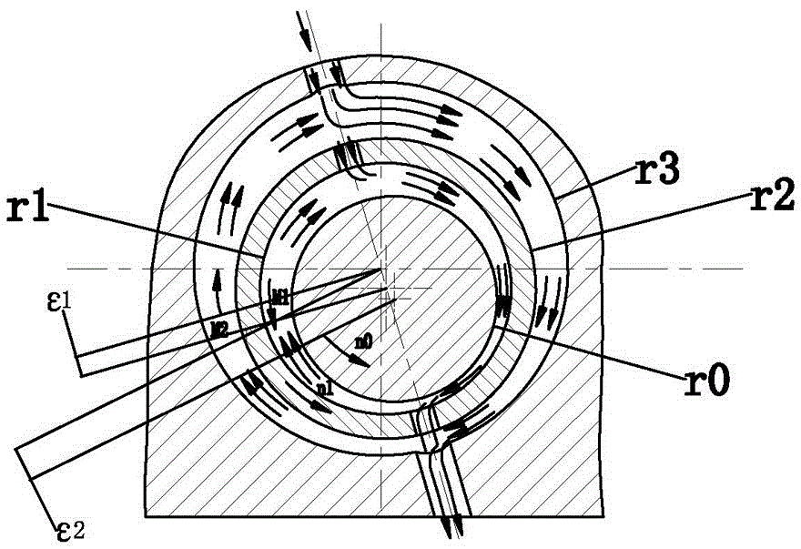
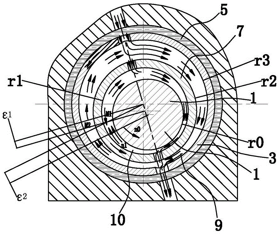
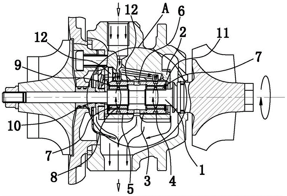
[0039] Such as image 3 As shown, the floating bearing structure used for a small turbocharger includes a single semi-floating bearing sleeve 3 that is sleeved on the turbine shaft 1 and positioned with the bearing body 2. In this embodiment, the bearing body 2 is pierced with a positioning Pin 12, the end portion of locating pin 12 radially penetrates one end of the single semi-floating bearing sleeve 3, so that the positioning of the single semi-floating bearing sleeve 3 and the bearing body 2 is convenient. There are several oil holes-4 on the single semi-floating bearing sleeve 3 and there is a static oil film gap 5 between the single semi-floating bearing sleeve 3 and the bearing body 2, and an oil return hole is open...


PUM


Abstract

The invention provides a floating bearing structure used for small turbochargers, and belongs to the technical field of machines. The problems of low efficiency, easy self-excited vibration, low durability and low stability of present bearing structures used for turbochargers. The floating bearing structure used for small turbochargers comprises a single semi-floating bearing sleeve, the single semi-floating bearing sleeve is provided with a plurality of oil holes I, a static oil clearance exists between the single semi-floating bearing sleeve and a bearing body, the single semi-floating bearing sleeve is provided with an oil return hole, a turbine rotating shaft is sheathed with a full-floating bearing sleeve, the full-floating bearing sleeve and the single semi-floating bearing sleeve are axially positioned, the full-floating bearing sleeve is provided with a plurality of oil holes II, a dynamic oil clearance I exists between the full-floating bearing sleeve and the single semi-floating bearing sleeve, and a dynamic oil clearance II exists between the full-floating bearing sleeve and the turbine rotating shaft. The floating bearing structure has the advantages of reasonable structure, high reliability, high efficiency and the like.

Description

technical field [0001] The invention belongs to the technical field of machinery and relates to a floating bearing, in particular to a floating bearing structure for a small turbocharger. Background technique [0002] At present, the technical quality of small turbochargers, whether foreign or domestic, has reached a very high level of optimization, and the space and potential for further excavation to improve the efficiency of the turbocharger shafting system are getting smaller and smaller. [0003] Floating bearings are divided into two types: full floating bearings and semi-floating bearings, such as figure 1 As shown, when n1=0, the full-floating bearing becomes a semi-floating bearing structure, and the arrow indicates the movement, bearing, and flow direction of the pressure lubricating oil film. As the speed of the turbocharger increases day by day, when n>40000r / min, ordinary sliding bearings are no longer competent, so most of the small turbochargers currently use...

Claims


Application Information

Patent Timeline
Patent Type & Authority Patents(China)
IPC IPC(8): F16C32/06F16C33/04F01D25/16
CPCF16C17/02F16C17/18F16C17/26F16C27/02F16C2360/24
Inventor 刘荣明吕茂周
Owner ZHEJIANG RONGFA MOTOR ENGINE
Why Eureka
Try Eureka