
A special tool holder for machining slender shafts

A technology of slender shaft and tool rest, which is applied in the direction of metal processing equipment, metal processing machinery parts, manufacturing tools, etc., can solve the problem of damage to the accuracy of tools and parts, machine tool precision skill level, demanding experience requirements, and slender shaft bending Deformation and other problems, to improve the processing quality and work efficiency, improve the rigidity of machine tools and processing technology, and solve the effect of bending deformation

Active Publication Date: 2017-07-07
48TH RES INST OF CHINA ELECTRONICS TECH GROUP CORP
View PDF11 Cites 0 Cited by
  • Summary
  • Abstract
  • Description
  • Claims
  • Application Information

AI Technical Summary

Problems solved by technology

In the turning process, due to its poor rigidity, the slender shaft is easily bent and deformed under the action of cutting force and cutting heat, which destroys the accuracy of the relative movement of the tool and the part, and causes the processed slender shaft to be deformed. The shape of thick in the middle and thin at both ends seriously affects the processing accuracy of the parts. At the same time, the bending deformation of the slender shaft will also cause vibration of the process system and affect the roughness of the parts. It is difficult to guarantee the processing quality requirements of the slender shaft; The slender shaft has extremely strict requirements on the precision and rigidity of the machine tool and the skill level and experience of the processor

Method used


Image

  • A special tool holder for machining slender shafts
  • A special tool holder for machining slender shafts

Examples


Embodiment Construction

[0022] It should be noted that, in the case of no conflict, the embodiments of the present invention and the features in the embodiments can be combined with each other. The present invention will be described in detail below with reference to the accompanying drawings and examples. For the convenience of description, if the words "up", "down", "left" and "right" appear in the following, it only means that the directions of up, down, left and right are consistent with the drawings themselves, and do not limit the structure.

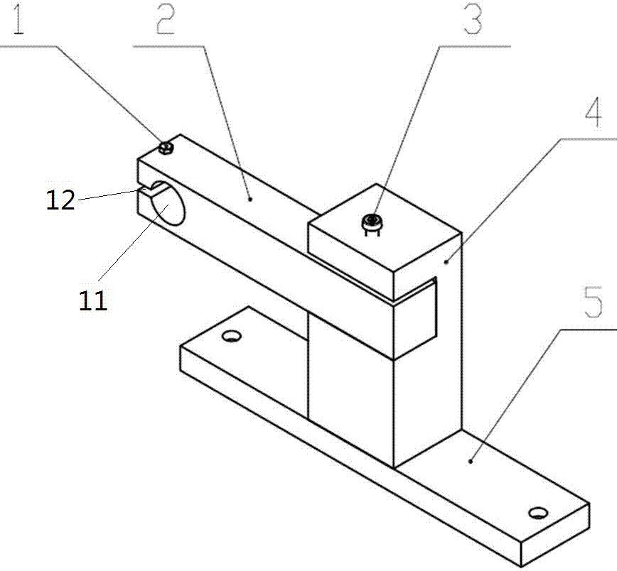
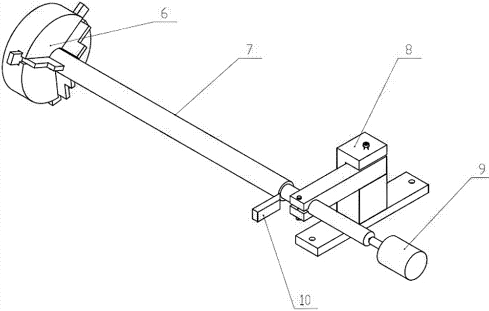
[0023] Such as Figure 1-2 As shown, the special tool holder for processing the slender shaft of the present embodiment includes a base 5, a column 4 and a support block 2; the base 5 and the support block 2 are connected to the column 4; the support block 2 has a through hole; An adjustment screw 1 passing through the support block 2 is provided at the through hole, and the expansion and contraction of the adjustment screw 1 makes the support block 2 el...


PUM


Abstract

The invention provides a purpose-made follow rest for machining slender shafts. The purpose-made follow rest for machining the slender shafts comprises a base, a stand column and a supporting block, wherein the base and the supporting block are connected with the stand column, a clamping through hole is formed in the supporting block, an adjusting threaded rod is arranged in the clamping through hole, and the supporting block makes elastic deformation through stretching and contraction of the adjusting threaded rod so that the size of the clamping through hole can be adjusted. According to the purpose-made follow rest for machining the slender shafts, influences caused by radial cutting force on the slender shafts can be effectively reduced, processing technology rigidity of a machine tool is improved, machining quality and working efficiency of the slender shafts are greatly improved, and operation is easy to carry out and practical.

Description

technical field [0001] The invention relates to the field of machine tool processing, in particular to a special tool holder for processing slender shafts. Background technique [0002] The processing and manufacturing industry is the pillar industry of our country's national economy. In the field of mechanical processing, the design of fixtures is particularly important, and it is the key technology for processing important parts. However, the process is complicated and the precision requirements are high. The rationality of its design not only determines the success or failure of the project , but also save a lot of manpower and material resources. [0003] Turning of slender shafts is a relatively common processing method in mechanical processing. Usually, shafts whose length to diameter ratio is greater than 20-25 (ie L / d≥20-25) are called slender shafts. In the turning process, due to its poor rigidity, the slender shaft is easily bent and deformed under the action of ...

Claims


Application Information

Patent Timeline
Patent Type & Authority Patents(China)
IPC IPC(8): B23Q1/76
CPCB23Q1/766B23Q2240/007
Inventor 谢辉舒勇东彭志虹刘洪文方灿东
Owner 48TH RES INST OF CHINA ELECTRONICS TECH GROUP CORP
Learn More