
An electrical arc extinguishing device

A technology of an arc extinguishing device and an air blowing device, which is applied in the electrical field, can solve problems such as adverse effects of switching components, achieve the effect of strengthening the cutting arc and increasing the arc extinguishing speed

Active Publication Date: 2016-05-25
上海耐吉电力集团有限公司
View PDF4 Cites 0 Cited by
  • Summary
  • Abstract
  • Description
  • Claims
  • Application Information

AI Technical Summary

Problems solved by technology

However, such a high thermal load can adversely affect the switching components

Method used


Image

  • An electrical arc extinguishing device
  • An electrical arc extinguishing device
  • An electrical arc extinguishing device

Examples


Embodiment 1

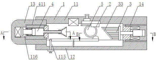
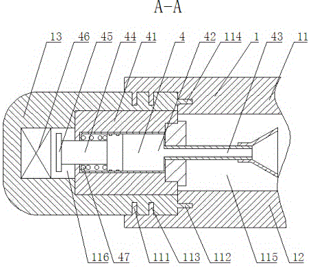
[0029] refer to Figure 1 to Figure 3 As shown, an electrical arc extinguishing device provided by the present invention includes a housing 1, a switch contact 2 arranged inside the housing 1, the contact includes a moving contact and a static contact, and also includes a The grid device 3, the air blowing device 4 for blowing the arc horizontally, the electromagnetic device 5 for creating a magnetic field between the moving contact and the static contact,

[0030] The grid device 3 is arranged opposite to the blowing device 4, the contact 2 is located between the grid device 3 and the blowing device 4, and the electromagnetic device is arranged on both sides of the contact 2,

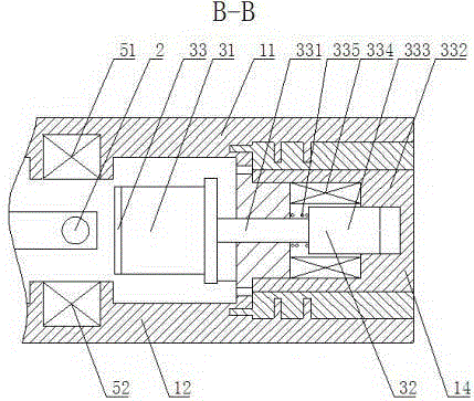
[0031] The grid device 3 includes a plurality of groups of parallel metal grids 31 opposite to the contact 2, each metal grid 31 is connected with a driving device 32, and the driving device 32 drives the metal grid when the contact 2 is disconnected. The sheet 31 moves toward the middle of the contac...

Embodiment 2

[0041] refer to Figure 5 As shown, the main difference between this embodiment and Embodiment 1 is that the driving device 32 includes a slide bar 321, one end of the slide bar 321 is connected with each metal grating 31, and the other end of the slide bar 321 is provided with a The fourth electromagnet 322 in the sleeve 323 and the sliding rod 321 pass through the sliding sleeve 323 , the sliding sleeve 323 is connected with the housing 1 , and a first spring 324 is provided between the sliding sleeve 323 and the sliding rod 321 . It is also possible to use other driving devices 32 to drive the metal grid sheet 31 without affecting the implementation of the present invention.


PUM


Abstract

The invention discloses an electric arc extinguishing device, which includes a grid sheet device for cutting the arc, an air blowing device for blowing the arc horizontally, and an electromagnetic device for creating a magnetic field between the moving contact and the static contact. The invention divides the arc into a series of short arcs through the grid device; and blows the arc horizontally through the air blowing device, which can bend and blow the arc to length, and extinguish the arc through cooling and diffusion, and the arc bends toward the grid device, further strengthening the grid. The role of the grid device to cut the arc, the electromagnetic device is used to create a magnetic field between the contacts, and the arc is bent to the grid device through the Lorentz force, which also strengthens the function of the grid device to cut the arc, through the grid device, blowing device , The electromagnetic devices cooperate with each other to extinguish the arc, and the driving device drives the grid device to move to the direction of the arc, and the air blowing device and the electromagnetic device drive the arc to move to the grid device, which greatly improves the arc extinguishing speed.

Description

technical field [0001] The invention relates to the field of electrical technology, in particular to an electrical arc extinguishing device. Background technique [0002] The arc extinguishing device is used to interrupt or extinguish the arc generated when a pair of current-carrying contacts are disconnected. As the contacts separate from each other, current flows in a correspondingly smaller contact area, causing the temperature in this area to gradually increase. A fusing bridge will be generated at the moment before the contacts are separated, and the fusing bridge will eventually break when the current is small; when the current is high, the fusing bridge will evaporate. The current can therefore only continue to flow through an arc in the form of a conductive plasma column. [0003] The type and magnitude of the switching current will have an effect on the strength of this arc. When a short circuit occurs in a circuit protected by a line protection switch, a short c...

Claims


Application Information

Patent Timeline
Patent Type & Authority Patents(China)
IPC IPC(8): H01H9/30H01H9/34H01H9/44
Inventor 林勇
Owner 上海耐吉电力集团有限公司
Learn More