
Plant inspection method and system

An inspection system and plant technology, applied in the field of inspection, can solve the problems of statistical sorting, time-consuming and laborious, difficult and accurate execution of material preparation or maintenance, etc., to reduce the error rate and reduce the labor burden.

Inactive Publication Date: 2014-10-29
LUMAX INT CORP
View PDF4 Cites 4 Cited by
  • Summary
  • Abstract
  • Description
  • Claims
  • Application Information

AI Technical Summary

Problems solved by technology

[0004] However, with the development of industrialization, the number and types of equipment in the plant are also increasing. Usually, a plant will be equipped with dozens, hundreds, or even thousands of instrumentation equipment, and the equipment according to its type and attribute, also There may be a variety of different items to be tested, so the types and items of the inspection table will be complicated and varied
Therefore, the above-mentioned method of obtaining the corresponding inspection form by inspection personnel for inspection is quite time-consuming and laborious in the execution of the process, resulting in low efficiency, and it is not fast enough for urgent inspections. The action of archiving the inspection table after the completion, because it cannot immediately carry out statistics and sorting of data with other related inspection tables, lacks the demand for real-time update, especially when it is necessary to target the inspection table corresponding to hundreds of thousands of devices It is a arduous and complicated work when sorting and sorting images, which not only consumes a lot of human resources, but also has a high error rate during sorting, which makes it difficult to carry out follow-up material preparation or maintenance preparations in advance, so it is necessary to carry out such tasks missing to improve

Method used


Image

  • Plant inspection method and system
  • Plant inspection method and system
  • Plant inspection method and system

Examples


Embodiment Construction

[0026] The present invention will be described in detail below in conjunction with the accompanying drawings and embodiments.

[0027] For the convenience of description, in the following embodiments, similar elements are denoted by the same reference numerals.

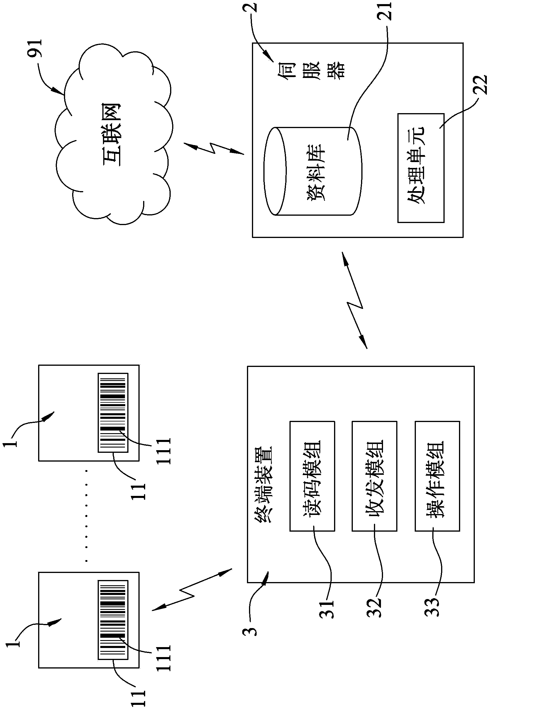
[0028] refer to figure 1 and figure 2 , is a first preferred embodiment of the plant inspection method of the present invention. During implementation, a plant inspection system is used for users to inspect multiple devices 1 of the plant. The devices 1 each have an identification element 11 . Each identification element 11 has a set of specific identification codes 111 built in. During implementation, the identification codes 111 can be presented in the form of one-dimensional barcodes, two-dimensional barcodes, numbers or radio frequency components. The identification codes of this preferred embodiment 111 is presented as a one-dimensional barcode.

[0029] The plant inspection system includes: a server 2 and a...


PUM


Abstract

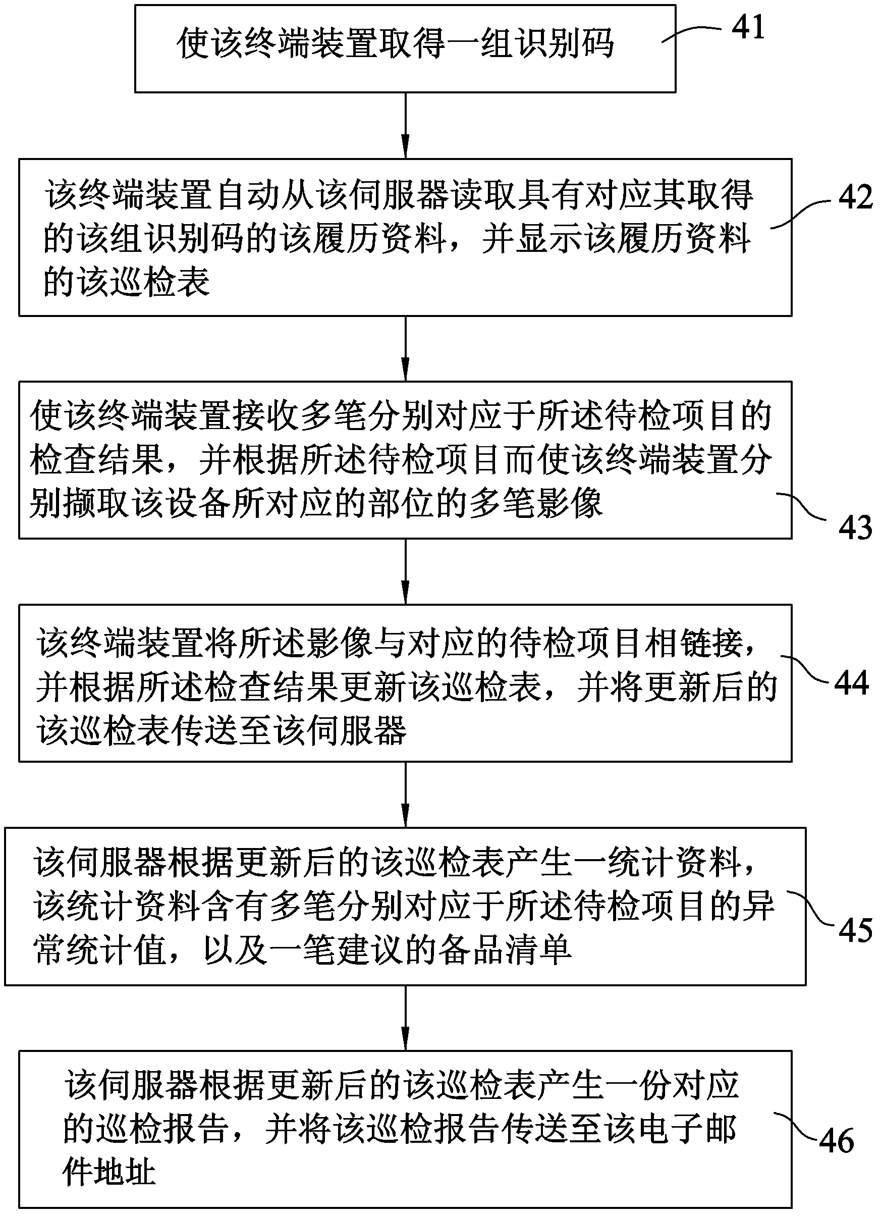
A plant inspection method and system. The method is suitable for implementation between a server and a terminal device, so that a user holding the terminal device can inspect the equipment of the plant. The server has multiple built-in biographical information corresponding to the equipment; and each biographical information includes a group of identification code and a inspection tour table including a plurality of projects to be inspected. The method comprises the following steps: (a) the terminal device acquires a group of identification codes; (b) the terminal device automatically reads biographical information corresponding to the group of acquired identification codes from the server, and displays the inspection table; (c) the terminal device receives a plurality of inspection results respectively corresponding to the projects to be inspected; and (d) the terminal device updates the inspection table according to the inspection results, and transmits the updated inspection table to the server.

Description

technical field [0001] The present invention relates to a patrol inspection method and system, in particular to a plant patrol inspection method and system suitable for checking plant equipment. Background technique [0002] Generally, in manufacturing factories, such as plastic factories, steel processing factories, component manufacturing factories, food processing factories, etc., all kinds of instruments and equipment will be set up in the factory building, and the automatic operation of these equipment will be used to complete production and manufacturing. Jobs that require finished / semi-finished products. Although the instruments and equipment will be different with different industrial attributes, no matter what kind of instrument equipment, regular inspections and maintenance are required, and even when serious faults and damages occur, diagnostic actions are required To facilitate follow-up maintenance, so as to ensure that all instruments and equipment can operate...

Claims


Application Information

Patent Timeline
Patent Type & Authority Applications(China)
IPC IPC(8): G07C1/20G07C1/10
Inventor 张新和王俊义吕岳泽钟元隆林俊宏
Owner LUMAX INT CORP
Learn More