
Method of constraining a safe operating area locus for a power semiconductor device

A technology of power semiconductor and safe working area, applied in semiconductor devices, electric solid state devices, instruments, etc., can solve the problem that the peak power is not significantly constrained

Active Publication Date: 2014-10-29
ROBERT BOSCH AUSTRALIA
View PDF6 Cites 1 Cited by
  • Summary
  • Abstract
  • Description
  • Claims
  • Application Information

AI Technical Summary

Problems solved by technology

However, the peak power is not significantly constrained when the drain current and drain-source voltage are at peak levels

Method used


Image

  • Method of constraining a safe operating area locus for a power semiconductor device
  • Method of constraining a safe operating area locus for a power semiconductor device
  • Method of constraining a safe operating area locus for a power semiconductor device

Examples


Embodiment Construction

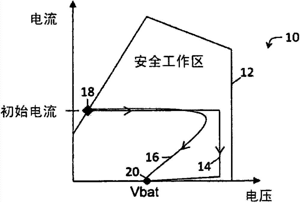
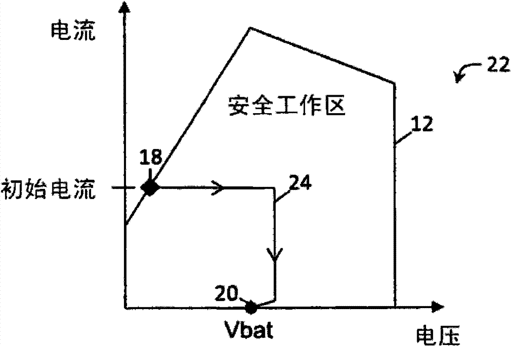
[0033] now refer to figure 2 , the positive offset safe operating area (SOA) trajectory 12 for the maximum ratio of the power semiconductor device is shown in graph 22 . As noted above, the SOA locus 12 represents the maximum simultaneous source-drain voltage and drain current that the power MOSFET can safely handle. In an embodiment of the present invention, the SOA trace 12 is constrained into a constrained SOA trace 24 with an N-channel enhancement mode power MOSFET in a high-side configuration between the power supply and the load. Those skilled in the art will appreciate that graph 22 may depict SOA trajectories for other devices, such as BJTs. Nevertheless, it can be seen that the source-drain voltage of the power MOSFET is constrained and the peak power generation as well as the total energy absorption of the power MOSFET is constrained to minimize the use of the SOA of the power MOSFET.

[0034] Constrained SOA trajectory 24 is generated according to the method desc...


PUM


Abstract

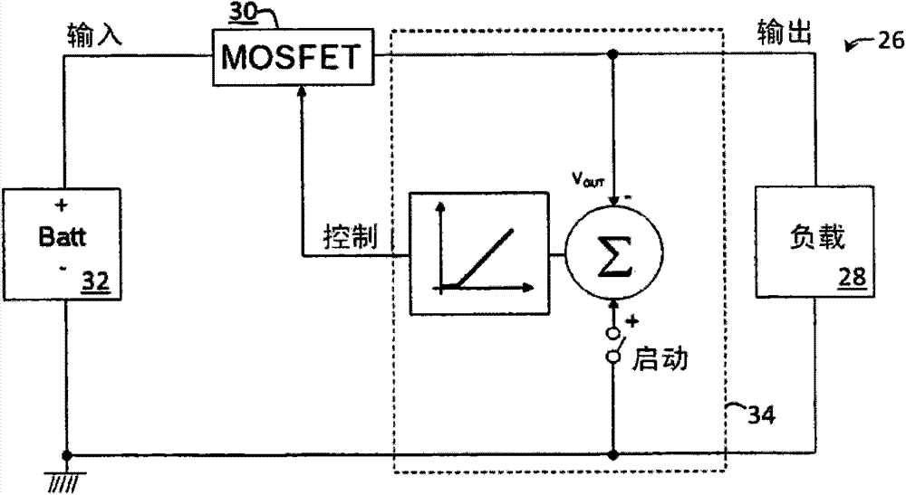
A method of constraining a Safe Operating Area (SOA) locus for a power semiconductor device during operation of the power semiconductor device placed between a power source and a load, the method including: taking a voltage measurement across the load (VLOAD); selecting a scalar for scaling the voltage measurement taken across the load (VLOAD); and constructing a control voltage for controlling the power semiconductor device with a control circuit according to the voltage measurement taken across the load (VLOAD) multiplied by the scalar so as to constrain an output voltage of the power semiconductor. <filename>

Description

technical field [0001] The present invention relates to methods and circuits for constraining the safe operating area (SOA) trajectory of a power semiconductor device located between a power supply and a load during operation of the power semiconductor device. The present invention has particular but not exclusive application to constraining the SOA locus of an N-channel enhancement mode power MOSFET in a high-side configuration between a power supply and a load by constructing a control voltage for controlling the power MOSFET to constrain the power MOSFET's The output voltage. Background technique [0002] Power semiconductor devices, such as power metal oxide semiconductor field effect transistors (MOSFETs), are typically used to switch power ON and OFF to inductive loads, eg, in automatic control and pulse width modulated motor control applications. The power MOSFET has a gate electrode for controlling the power MOSFET, a drain electrode connected to the power source, a...

Claims


Application Information

Patent Timeline
IPC IPC(8): G05F1/56
CPCH01L2924/0002H03K17/0822H01L2924/00
Inventor T·罗科
Owner ROBERT BOSCH AUSTRALIA
Learn More