cone connector

A connector and tapered technology, applied in the field of optical communication, can solve the problems of inability to meet the mechanical properties of the ferrule, breakage, affecting the transmission of optical signals, etc., to achieve the effect of fewer assembled components, reduced workload, and reduced production of finished products.

Active Publication Date: 2017-01-18
SICHUAN TIANYI COMHEART TELECOM
View PDF4 Cites 0 Cited by
  • Summary
  • Abstract
  • Description
  • Claims
  • Application Information

AI Technical Summary

Problems solved by technology

[0008] However, due to the structural characteristics of the butterfly optical cable, combined with the above-mentioned method of using ordinary connectors, after the ordinary tail handle is connected to the optical cable, it is pressed and fixed by the metal boot, which will cause the optical cable at the connection part to be fixed, and the ferrule cannot pass through. The elastic force generated by the movement of the optical fiber cannot meet the specified elastic force of the ferrule and meet the mechanical properties of the downward stroke of 0.6mm
At the same time, the connection between the optical cable and the ordinary connector is only an optical fiber, and the material of the optical fiber is quartz glass with an outer diameter of 250 μm, which cannot bear any external force at all. Fracture, thus affecting the transmission of optical signals

Method used


Image

  • cone connector
  • cone connector
  • cone connector

Examples


Embodiment

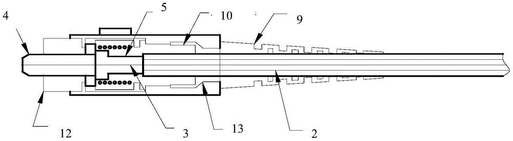
[0031] In this example the tapered connector, such as Figure 5 As shown, it includes a tapered tail handle 7 , ferrule 4 , shell 8 , boot 9 , positioning piece 10 , spring 11 and inner column 12 .

[0032] Wherein, the structure of tapered tail handle 7 and ferrule 4, such as Image 6 As shown, the tapered tail handle 7 is connected to the ferrule 4, the positioning member 10 is sleeved on the connecting part of the tapered tail handle 7 and the butterfly optical cable 6, and the inner column 12 is sleeved on the ferrule 4, and is connected with the The positioning elements 10 are connected.

[0033] Wherein, the tapered tail handle 7 is a tapered sleeve, and the inner side of the ferrule 4 is provided with a small hole, and the top of the tapered sleeve is fixedly connected with the ferrule 4, as Figure 7As shown, the front end of the butterfly optical cable 6 is stripped to form the bare fiber section at the front end, the strength member 2 and the coated fiber section a...


PUM


Abstract

The invention relates to a component in the field of light guide communication. The invention provides a conical connector aiming at the problem of poor mechanical property of connectors. According to the conical connector, a tail handle is connected with an insertion core; a location element sleeves the junction of the tail handle and an optical cable; an inner column is arranged on the insertion core in a sleeving manner, provided with a sealed end which is in contact connection with one end of the insertion core, and connected with the location element; the tail handle is a conical tail handle; the conical tail handle is a conical sleeve; a small hole is formed in the inner side of the insertion core; the top of the conical sleeve is fixedly connected with the other end of the insertion core; a bare optical fibre section is completely inserted in the small hole in the inner side of the insertion core from the bottom of the conical sleeve; a reinforcing element and a coated optical fibre section are arranged in the conical tail handle and fixed; an inner hole in one end of the location element is a conical inner hole matched with the conical tail handle, and an inner hole in the other end is a butterfly-shaped inner hole matched with a butterfly-shaped electric cable; the butterfly-shaped inner hole is formed in a butterfly-shaped optical cable portion at the junction of a butterfly-shaped optical cable and the conical tail handle; the conical inner hole end is arranged at the conical tail handle end in a sleeving manner, and the conical inner hole end is fixedly connected with an inner column open end. The conical connector is suitable for an optical fibre connector.

Description

technical field [0001] The invention relates to components in the field of optical communication, in particular to an optical fiber connector. Background technique [0002] As the future access network, fiber-to-the-home network is being deployed on a large scale in China. The main body of fiber-to-the-home applications is gradually popularized by public utility companies, municipalities, and some competitive local exchange operators to end users such as commercial and self-occupied buildings. [0003] In the application of fiber-to-the-home, as the main structure of the home-entrance cable—the butterfly-shaped drop-in cable is used more and more, and the butterfly-shaped cable needs to make connectors on site. In the prior art, the following two methods are mostly used. Connector method: [0004] 1. Made with field-assembled optical fiber active connectors; [0005] 2. Welding with pigtail; [0006] In the prior art, the second method is often used for making connectors...

Claims


Application Information

Patent Timeline
Patent Type & Authority Patents(China)
IPC IPC(8): G02B6/38
Inventor 李俊画马剑
Owner SICHUAN TIANYI COMHEART TELECOM
Why Eureka
Try Eureka