
Motor stator assembly and assembling method thereof, and motor

A technology for motor stators and components, applied in the direction of electric components, electrical components, electromechanical devices, etc., can solve the problems of increasing the axial space occupied by the motor, inconvenient winding, and long lead-out distance, so as to reduce the difficulty of winding, The effect of convenient wiring and reduced lead-out distance

Active Publication Date: 2014-10-22
GUANGDONG WELLING ELECTRIC MACHINE MFG
View PDF6 Cites 13 Cited by
  • Summary
  • Abstract
  • Description
  • Claims
  • Application Information

AI Technical Summary

Problems solved by technology

[0003] The purpose of the present invention is to provide a motor stator assembly, aiming to solve the problem of inconvenient winding and unfavorable installation of lead-out wire clips and wire clips from the wiring caused by the existing motor stator assembly terminals being arranged at the inner edge of the iron core teeth. The lead-out distance from the column to the outside of the stator is relatively long and will increase the space occupied by the motor in the axial direction

Method used


Image

  • Motor stator assembly and assembling method thereof, and motor
  • Motor stator assembly and assembling method thereof, and motor
  • Motor stator assembly and assembling method thereof, and motor

Examples


Embodiment Construction

[0031] In order to make the technical problems, technical solutions and beneficial effects to be solved by the present invention clearer, the present invention will be further described in detail below in conjunction with the accompanying drawings and embodiments. It should be understood that the specific embodiments described here are only used to explain the present invention, not to limit the present invention.

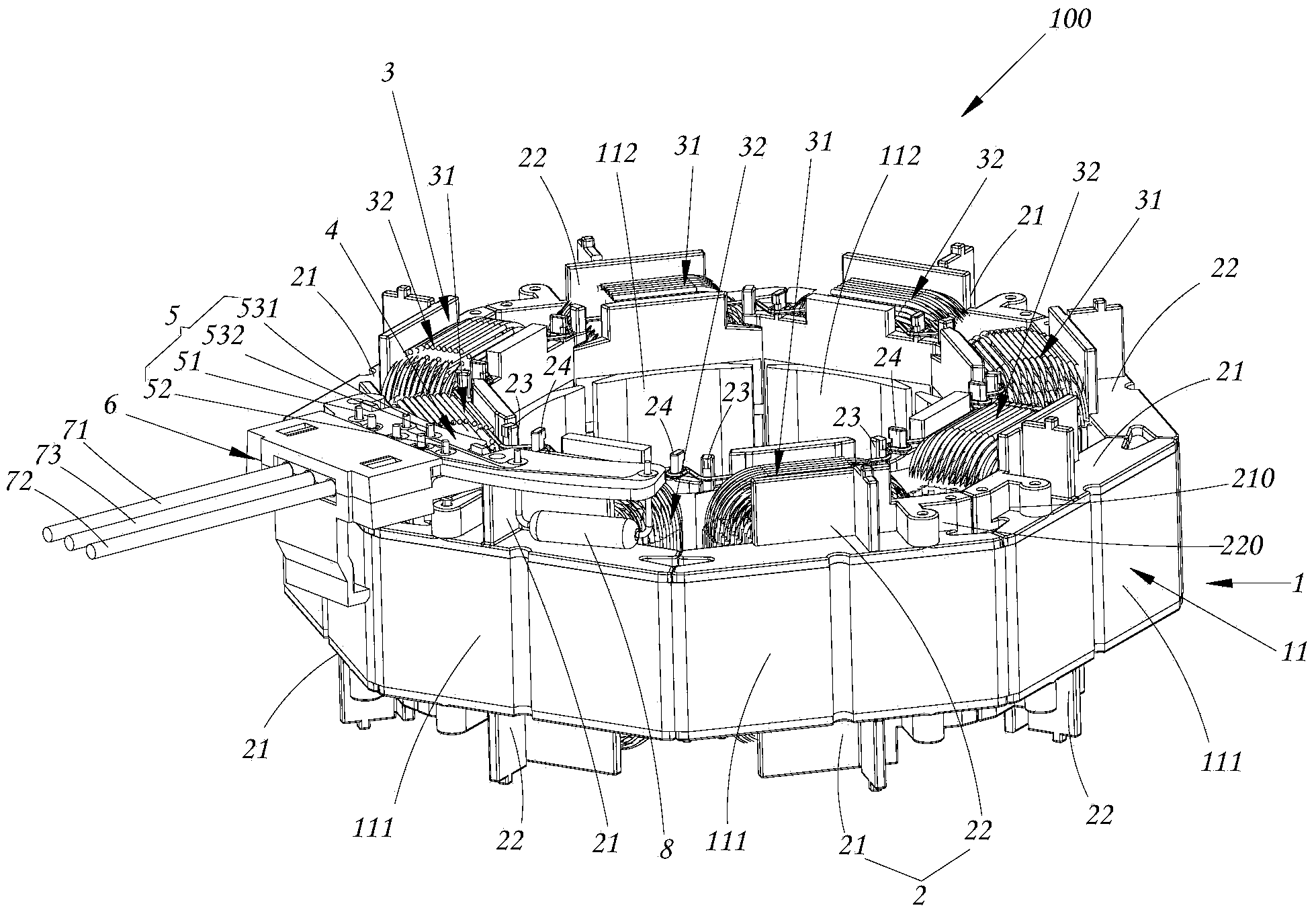
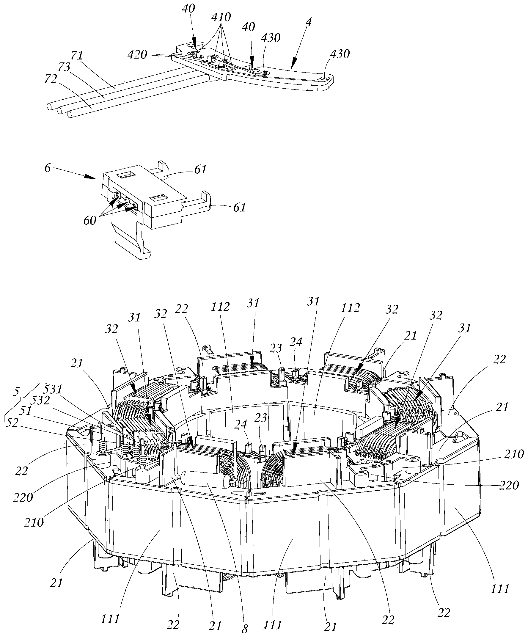
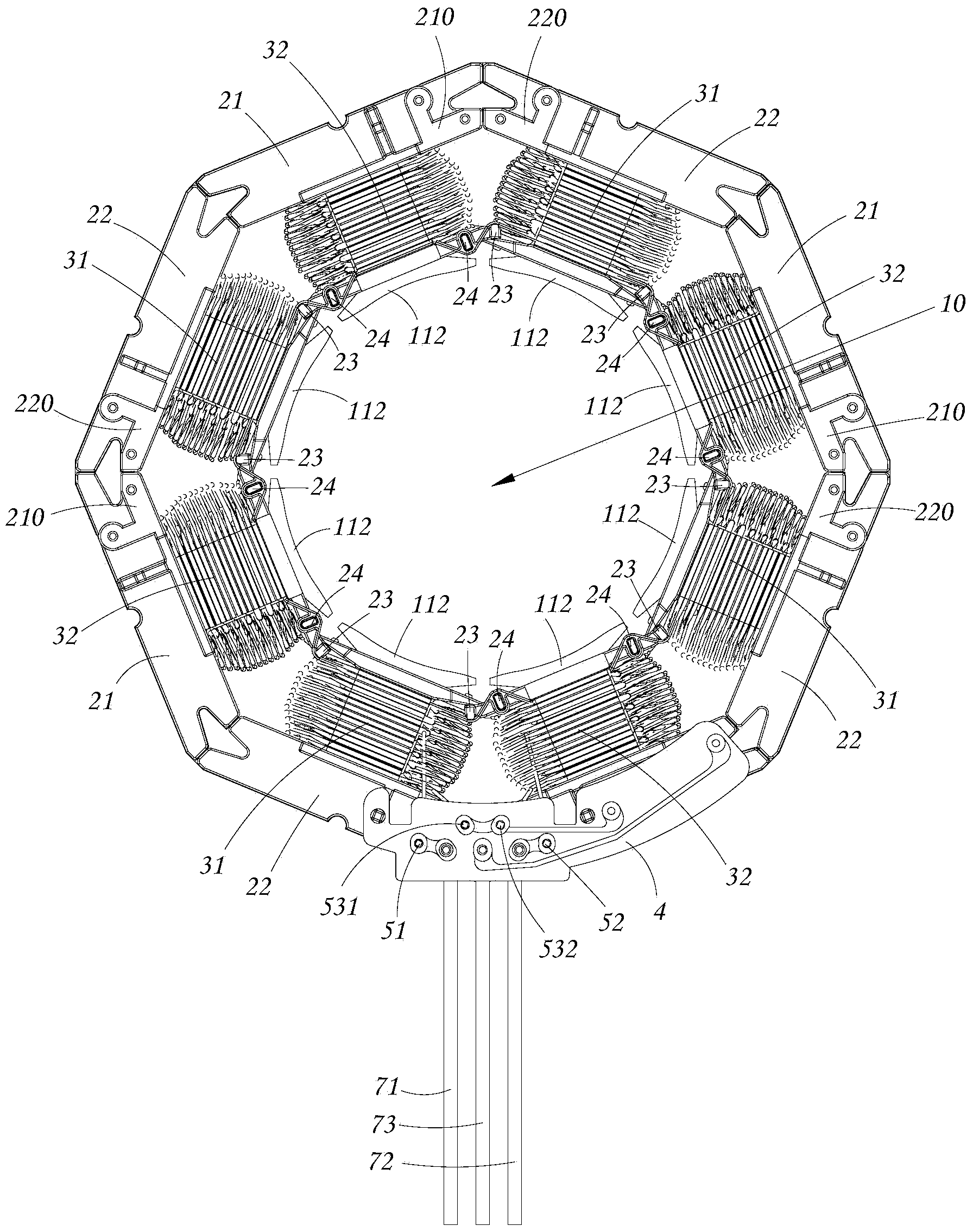
[0032] The motor stator assembly of the present invention includes a stator core, an insulating member arranged on the stator iron core, and a coil winding wound on the insulating member. The stator iron core has a yoke and several teeth arranged inside the yoke. The stator iron core There is an inner bore in the middle of the inner bore; on the insulating member and near the edge of the teeth of the inner bore, there is a wire passing mechanism for the winding of the coil winding to pass, and on the insulating member and near the outer edge of the yoke, there is a ...


PUM


Abstract

The invention provides a motor stator assembly and an assembling method thereof, and a motor. The motor stator assembly and a threading column of the motor are arranged at an internal edge, which is close to an iron core tooth part, of an insulating component. A connecting column assembly is arranged at an external side part of the insulating component so that the connecting column and an external winding machine can be arranged at the same side, winding is facilitated, and installation of a lead-out wire clamp is facilitated. Besides, lead-out distance from the connecting column to the external side of a stator is greatly reduced, and axial space occupation of the motor is reduced so that miniature design of the motor is facilitated. According to the assembling method of the motor stator assembly, multiple iron core single bodies from which an iron core is composed are divided into two groups with the identical number and assembled via a circular tooling respectively. The two groups of the iron core single bodies are respectively wound with a motor primary winding and a motor secondary winding via a winding machine, and then the complete stator assembly is assembled together. Winding is quite convenient due to a vacancy winding machine arranged between the adjacent iron core single bodies on the iron core single body groups so that winding difficulty is greatly reduced and production efficiency of the motor is enhanced.

Description

technical field [0001] The invention belongs to the technical field of motors, and more specifically relates to a stator assembly of a motor, an assembly method thereof and a motor. Background technique [0002] The traditional motor stator core end insulator is equipped with holes for installing terminal posts, wire passing posts and other structures. However, the wire passing posts, wire fixing posts and terminals electrically connected to the circuit board are all set on the insulating member close to the iron core. The inner edge of the teeth, therefore, the terminal is on the opposite side to the external winding machine, so that the winding is very inconvenient, and it is also not conducive to the installation of the lead-out wire clip, and the lead-out distance of the wire clip from the terminal to the outside of the stator is relatively long. At the same time, it will increase the axial space occupied by the motor, which is not applicable if the internal axial space ...

Claims


Application Information

Patent Timeline
IPC IPC(8): H02K1/14H02K3/52H02K3/50H02K15/02H02K15/08
CPCH02K1/16H02K3/50H02K5/225H02K15/0062H02K15/0068H02K2203/09
Inventor 万为君文凯平
Owner GUANGDONG WELLING ELECTRIC MACHINE MFG
Learn More